
Backlight unit with corner light source

a backlight unit and corner light source technology, applied in the field of backlight units, can solve the problems of insufficient illumination and exacerbate the non-uniform luminance deficiency, and achieve the effect of minimizing luminance variations

Inactive Publication Date: 2012-07-26
LG ELECTRONICS INC
View PDF4 Cites 20 Cited by
  • Summary
  • Abstract
  • Description
  • Claims
  • Application Information

AI Technical Summary

Benefits of technology

[0013]To address the above drawbacks, a one primary objective of the present invention is to provide a backlight unit that is capable of minimizing luminance variations of an liquid crystal display (LCD) panel having a limited number of LED chips employed in the panel's light source unit.
[0016]In this arrangement, radiated light can be introduced via two surfaces of the LCD panel or at least a portion of the radiated light is transmitted via two surfaces at the LCD panel that are facing each other. Hence, an area with the highest luminance (also referred to herein as ‘spot’ area) generated by the light source unit is emitted towards areas surrounding of the corner of the liquid crystal panel, thereby minimizing luminance variations over the LCD panel when a limited number of LED chips is employed (e.g., when only a single LED chip or a pair of LED chips is / are employed). In an embodiment, the light source unit may be spaced apart from the LCD panel by a preset distance, which may employ adjustable spacing implements to further reduce spot areas at the LCD panel.
[0017]In addition, the LCD panel may be located within a radiation range of the light source unit, namely, within an entrance angle thereof, thereby further reducing the luminance differentiation of an illuminated LCD panel.

Problems solved by technology

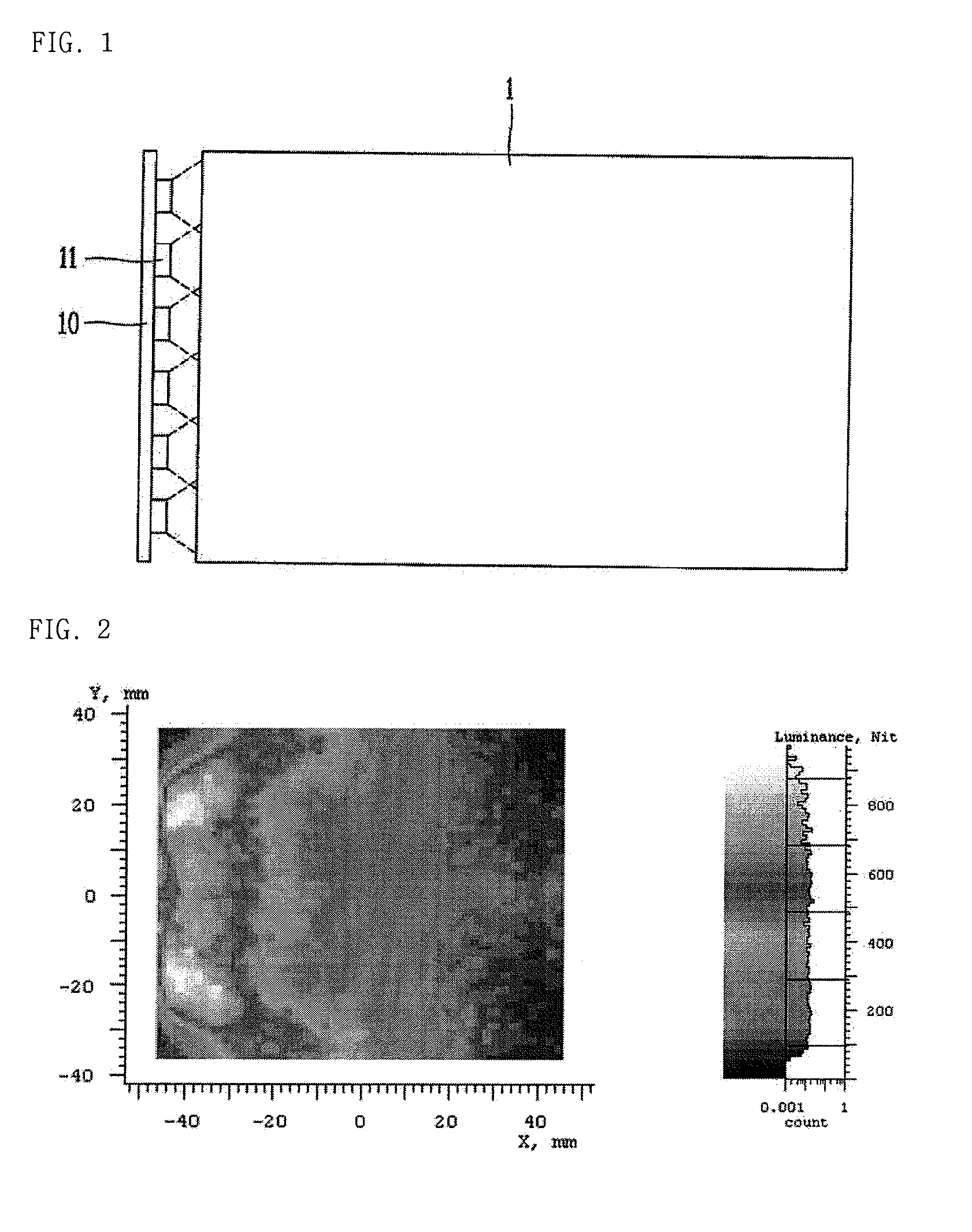
In accordance with FIG. 2, where only one LED chip is provided, the lighting provided is insufficient due to a drastic variations of luminance of the entire LCD panel.
However, use of the high-luminance LED chip in the above lighting scenarios exacerbates the non-uniform luminance deficiency.

Method used


Image

  • Backlight unit with corner light source
  • Backlight unit with corner light source
  • Backlight unit with corner light source

Examples


Embodiment Construction

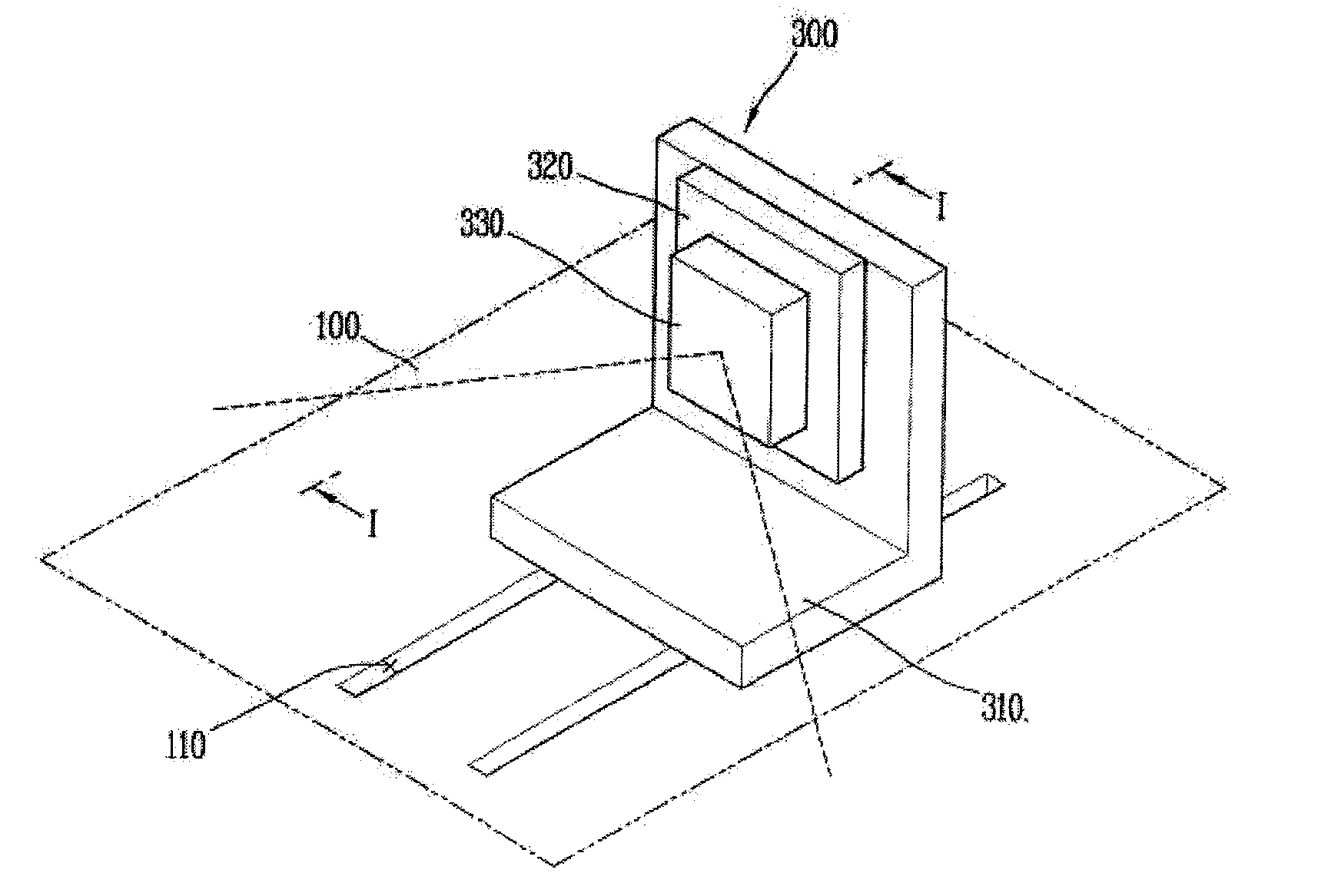
[0029]Description will now be given in detail of a backlight unit having a corner light source in accordance with the exemplary embodiments of the present disclosure, with reference to the accompanying drawings. For the sake of brief description with reference to the drawings, the same or equivalent components will be provided with the same reference numbers, and corresponding description thereof will not be repeated.

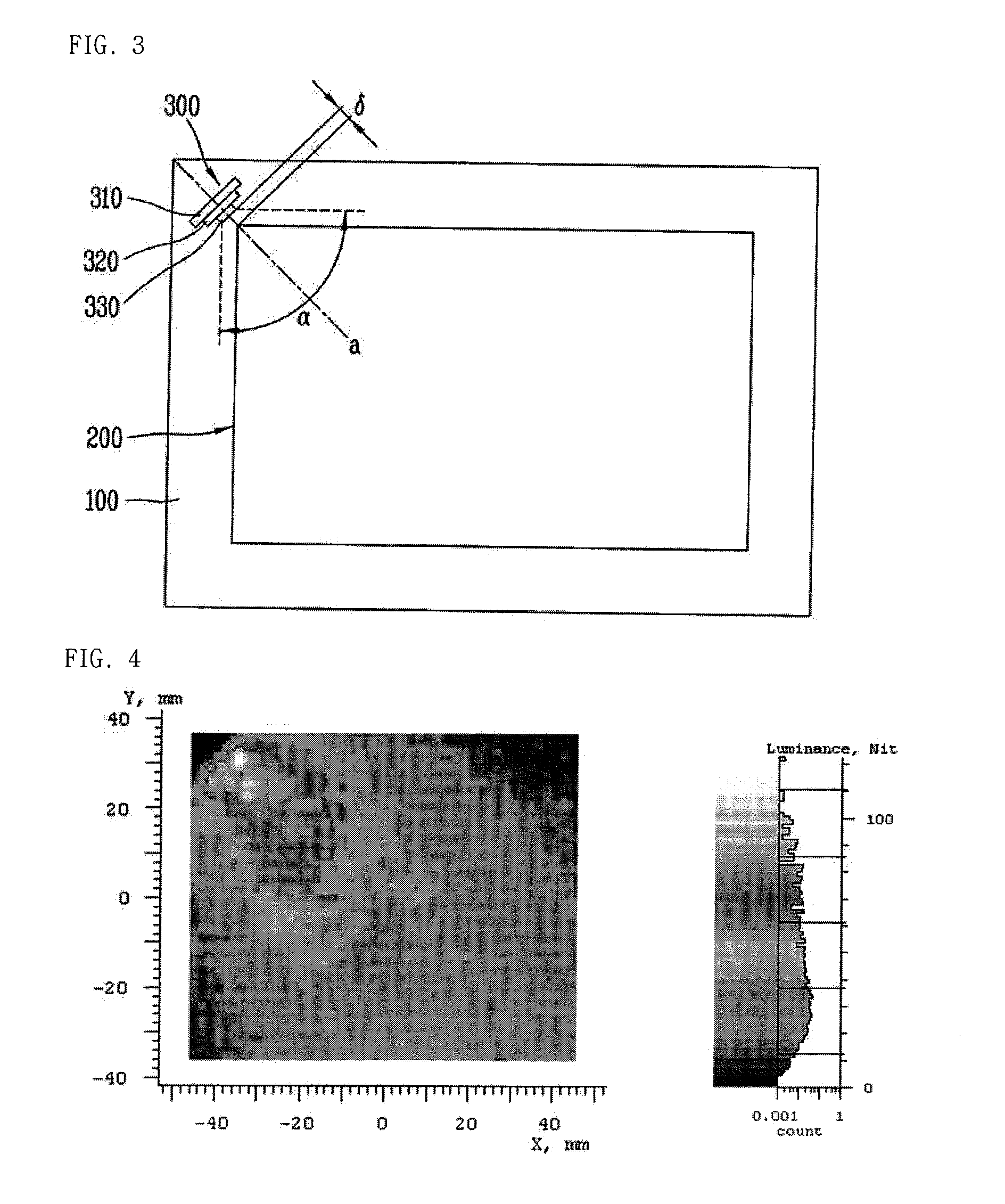
[0030]FIG. 3 is a planar view showing an LCD panel having a backlight unit in accordance with one exemplary embodiment of this specification. FIG. 4 is a view showing a corresponding luminance distribution associated with the embodiment of FIG. 3.

[0031]As shown in FIGS. 3 and 4, the LCD panel may include a bottom sash 100. The bottom sash 100 is a member for providing a space for mounting an optical unit 200 and the light source unit 300. The optical unit 200 may be disposed on an upper surface of the bottom sash 100. The optical unit 200 may include an optical sheet 21...


PUM

PropertyMeasurementUnit
distanceaaaaaaaaaa
distanceaaaaaaaaaa
radiation angleaaaaaaaaaa

Abstract

A backlight unit having a corner light source unit includes an optical unit having an optical sheet stacked on a bottom sash, and a liquid crystal display panel stacked on the optical sheet, and a light source unit located at the bottom sash to allow radiated light to be transferred to the liquid crystal display panel via two surfaces of the liquid crystal display panel.

Description

CROSS-REFERENCE TO A RELATED APPLICATION[0001]This application claims priority to Korean Patent Application No. 10-2011-0005695, filed on Jan. 20, 2011, which is herein expressly incorporated by reference in its entirety.BACKGROUND OF THE INVENTION[0002]1. Field of the Invention[0003]The subject matter of the disclosure generally relates to improved backlight units that are associated with devices having a liquid crystal display panel.[0004]2. Background of the Invention[0005]A Liquid Crystal Display (LCD) panel is unable to emit light without the aid of a backlight unit, which is a separate device for supplying light thereto.[0006]Different types of backlight units include: a Cold Cathode Fluorescent Lamp (CCFL), an External Electrode Fluorescent Lamp (EEFL), a Light Emitting Diode (LED), a Flat Fluorescent Lamp (FFL), and the like. In recent years, backlight units using LED-based backlight units have been found to be particularly advantageous with respect to enhanced optical quali...

Claims


Application Information

Patent Timeline
Patent Type & Authority Applications(United States)
IPC IPC(8): G02F1/13357
CPCG02B6/0068G02B6/0091G02B6/009G02B6/0073G02F1/133615G02F2201/46
Inventor CHEON, KANGWOON
Owner LG ELECTRONICS INC
Learn More