
Luminous means

a technology of luminous devices and luminous tubes, which is applied in the field of luminous devices, can solve the problems of high cost and time expenditure, unsuitable replacement tubes, and high power consumption of conventional fluorescent tubes, and achieve the effect of convenient maintenance and repair of luminous devices, and quick and easy installation

Inactive Publication Date: 2012-07-26
DIEHL AEROSPACE GMBH
View PDF3 Cites 10 Cited by
  • Summary
  • Abstract
  • Description
  • Claims
  • Application Information

AI Technical Summary

Benefits of technology

[0005]The object of the invention is to eliminate the disadvantages in accordance with the prior art. In particular, the invention specifies a luminous means which can be used as a replacement for conventional fluorescent tubes without a high level of complexity being involved. In accordance with a further aim of the invention, the luminous means can be used in particular as a replacement for conventional fluorescent tubes in the sector of aircraft cabins and should meet the safety requirements relevant for this sector.
[0010]The use of the luminous means according to the invention does not necessitate any change to the on-board power supply system or the conventional holders for the fluorescent tubes. Nevertheless, the luminous means makes it possible to save energy and at the same time enables substantially more extensive adjustment of the luminous characteristic owing to the use of a luminous device comprising LEDs.
[0016]In the case of an aircraft cabin, the luminous device according to the invention makes use of a conventional installation for fluorescent tubes, i.e. it is possible in particular for the already existing on-board power supply system with power supply lines and signal lines, the holders for the fluorescent tubes and the conventional lighting controller connected to the signal lines to be used. For the operation of the luminous means according to the invention, however, a data transmitter for transmitting the data for adjusting the luminous characteristic to the data receiver accommodated in the luminous means is also included. On the basis of a conventional luminous device, in which conventional fluorescent tubes are used, the luminous device according to the invention can be produced in a relatively simple manner. For this purpose, only the conventional fluorescent tubes need to be replaced by the luminous means according to the invention, and the data transmitter also needs to be provided. Expediently, the data transmitter is integrated in the lighting controller or is connected to the lighting controller, with the result that data can therefore advantageously only be transmitted when the data receiver has already been activated or made activatable by means of the controller.
[0018]In a further advantageous configuration, a plurality of luminous means is provided, with each of the data receivers of said luminous means being provided with a specific address. In this case, a luminous characteristic of each of the luminous means can be adjusted individually by means of the data transmitter. It is thus possible to produce complex lighting scenarios within a cabin. For this purpose, the data transmitted by the data transmitter are advantageously generated by means of a predetermined computer program. Different lighting scenarios can therefore be produced easily and quickly. It is possible for different lighting scenarios to be produced at different locations in the cabin at the same time.
[0020]In accordance with a further advantageous configuration, the data transmitter is configured as a second data transceiver. The information items relating to a function state of the luminous means can be received by such a second data transceiver. It is thus possible, for example, to establish quickly and easily whether there is an operational fault in a luminous means. This facilitates maintenance and repair of the luminous device.

Problems solved by technology

Conventional fluorescent tubes consume a relatively high power.
Such “replacement tubes” are not suitable, however, for replacing fluorescent tubes in aircraft cabins since the signal lines provided there do not enable driving of the LED controller.
This results in a high level of costs and time expenditure.

Method used


Image

  • Luminous means
  • Luminous means
  • Luminous means

Examples


Embodiment Construction

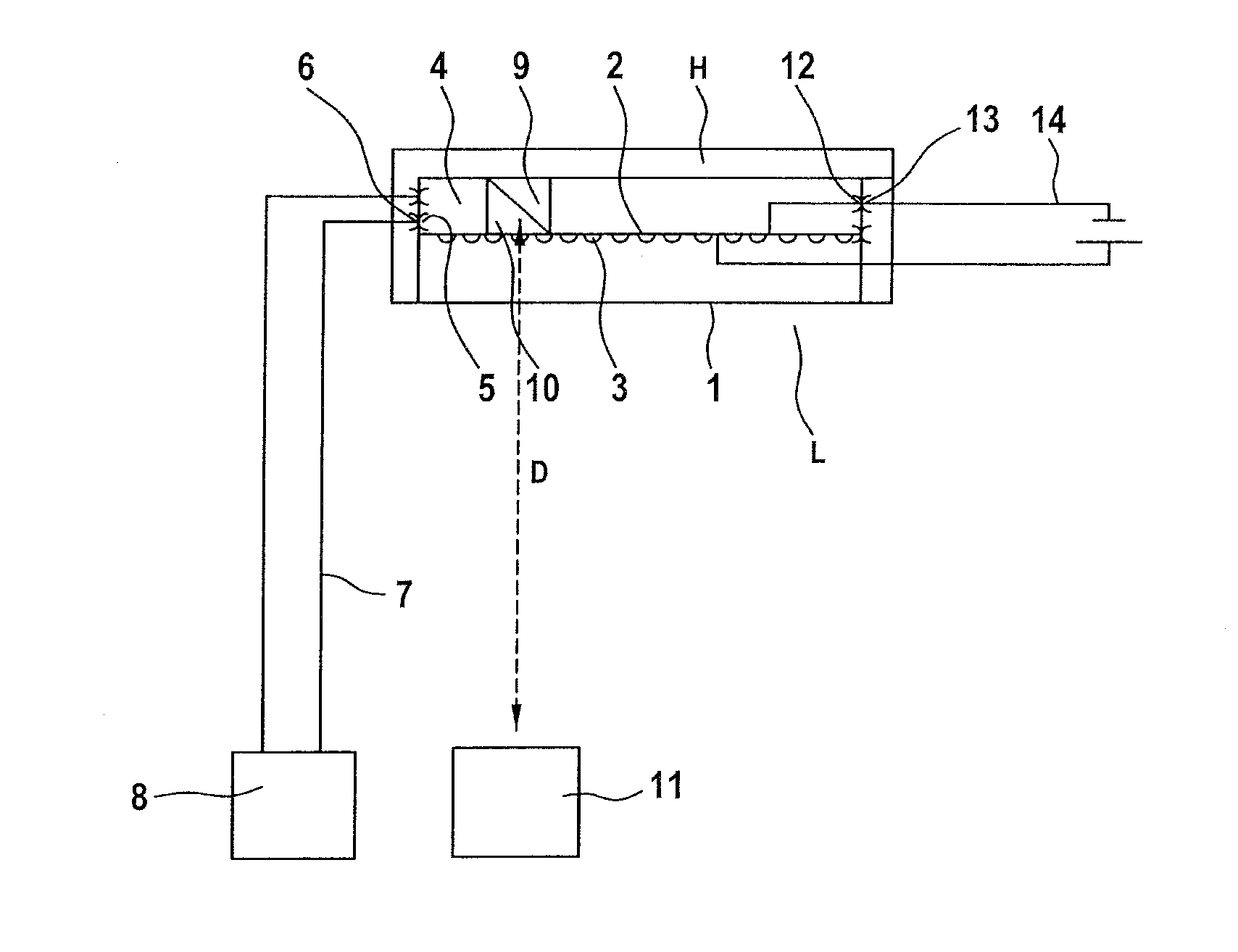
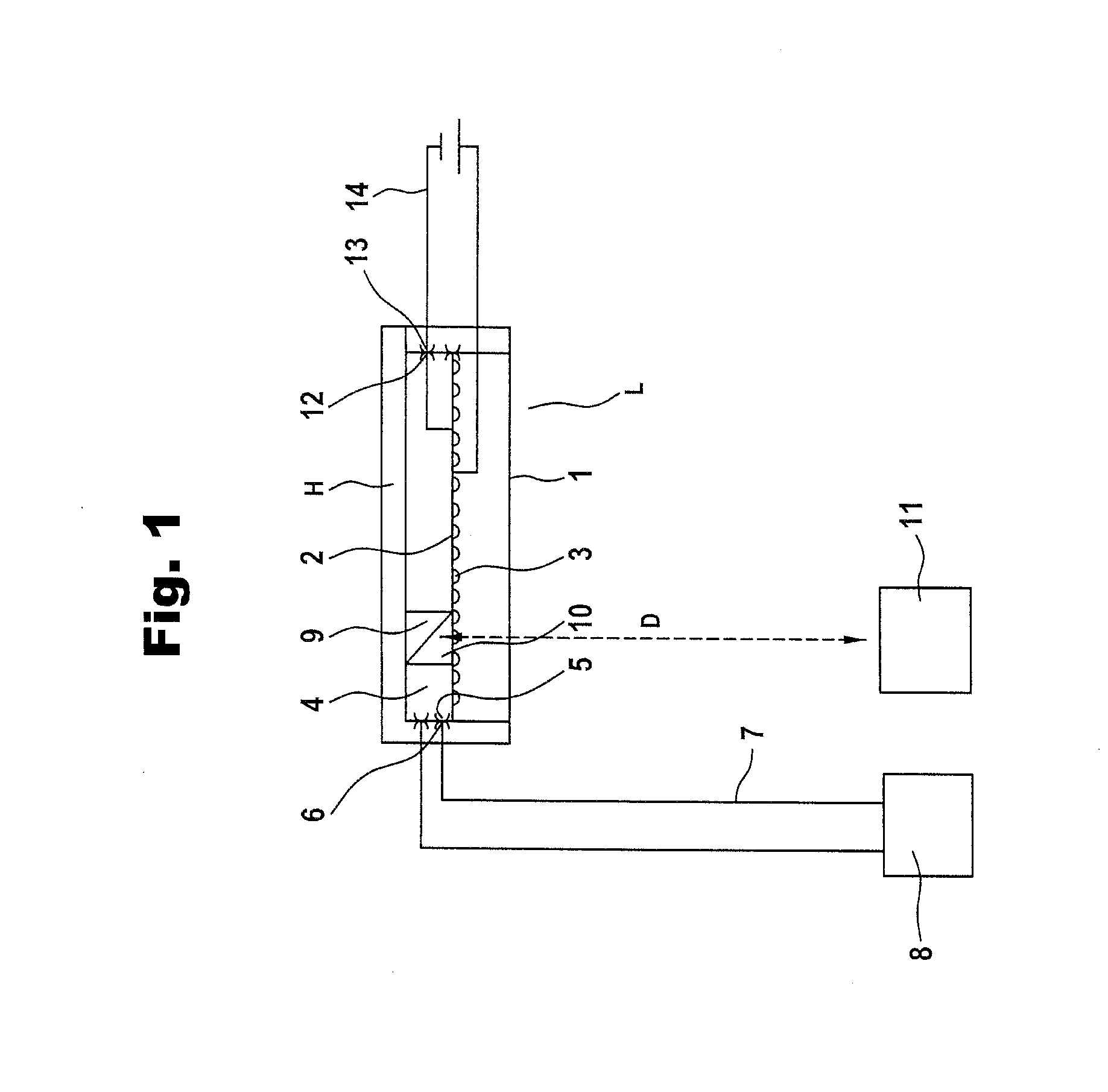
[0025]In FIG. 1, a luminous means which is generally denoted by the reference symbol L is accommodated in a holder H. The luminous means L has a housing 1, for example a tubular housing, in which a luminous device 2 is accommodated which has a large number of LEDs 3 for generating light. The reference symbol 4 denotes a controller accommodated in the housing 1. First contacts 5 of the controller 4 are in electrical contact with first mating contacts 6, which connect signal lines 7 to a lighting controller 8.

[0026]The reference symbol 9 denotes an LED controller which is connected to a data receiver 10 for wireless reception of data. The data receiver 10 can be in the form of a first data transceiver, which is suitable both for receiving and transmitting data.

[0027]Reference symbol 11 denotes a data transmitter for wireless transmission of the data D. The data transmitter 11 can be a second data transceiver, which is suitable for both transmitting and receiving data D.

[0028]The lumin...


PUM


Abstract

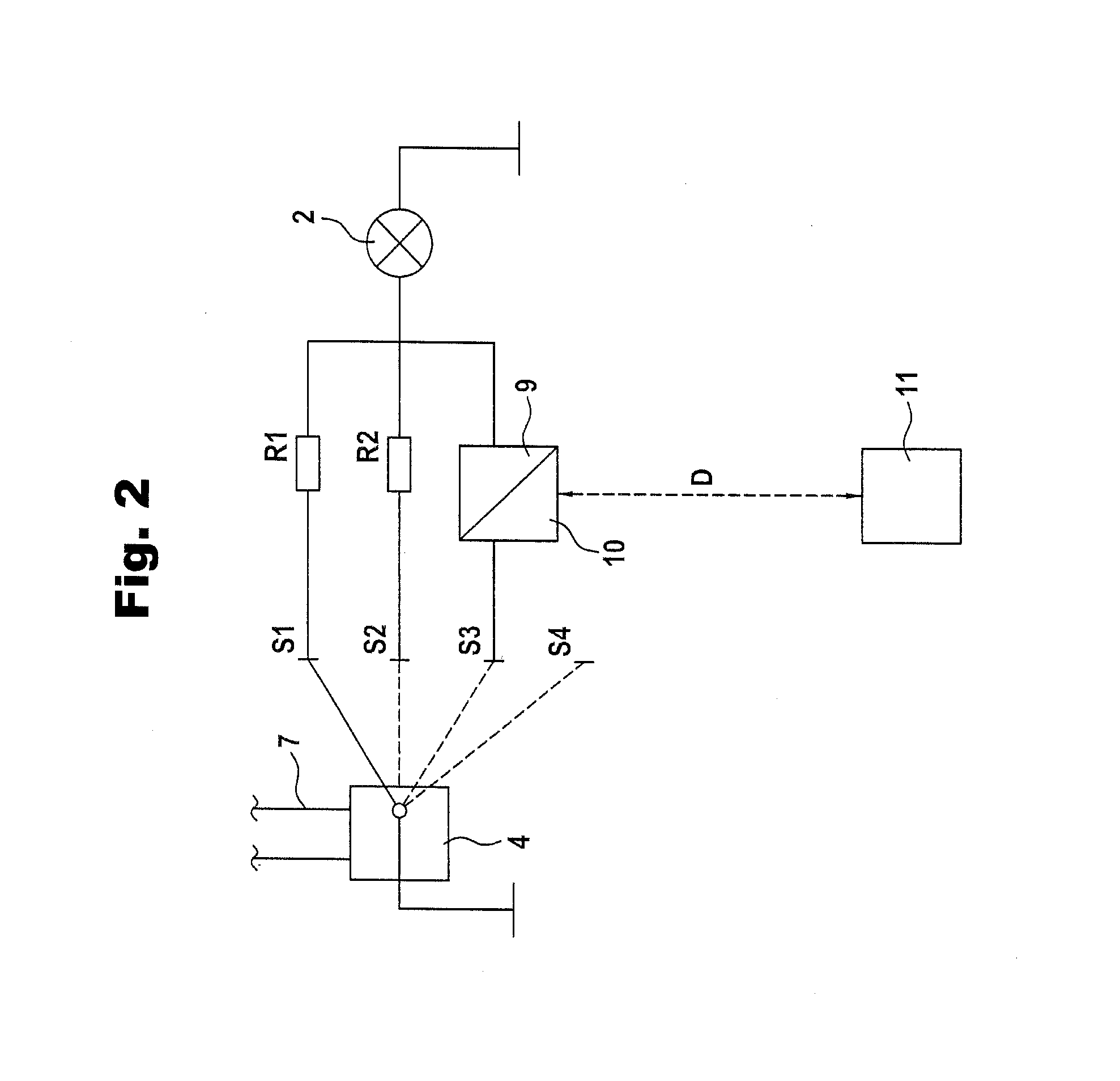
A luminous device is provided comprising LEDs with an LED controller for adjusting a luminous characteristic of the LEDs, and a data receiver (10). The data receiver (10), is connected to the LED controller (9), for wireless reception of data (D). The controller (4) is configured in such a way that, in predetermined switching stage (S3) of the controller (4), the data receiver (10) can be or is activated, and in the case of an activated data receiver (10), the luminous characteristic of the LEDs (3) can be adjusted exclusively by the LED controller (9) depending on data (D) received by the data receiver (10).

Description

BACKGROUND OF THE INVENTION[0001]The invention relates to a luminous means for lighting a cabin, in particular a cabin of a land vehicle or aircraft.DISCUSSION OF THE PRIOR ART[0002]In accordance with the prior art, fluorescent tubes are used in particular for lighting aircraft cabins. Such fluorescent tubes are provided with a luminous device which is surrounded by a housing which is configured in such a way that at least a section of said housing is transparent. In addition, a controller is provided in the housing, said controller enabling stepwise adjustment of a brightness of the luminous device. The on-board power supply system of an aircraft comprises two signal lines, which are connected to the controller via first contacts provided on the housing of the luminous means. In addition, the luminous means is also connected to a power supply via second contacts provided on the housing. By means of the controller, the luminous means can be switched off completely during takeoff or ...

Claims


Application Information

Patent Timeline
IPC IPC(8): B60Q3/02
CPCB60Q3/0259B60Q2900/10B64D2203/00B64D47/02B64D2011/0038B60Q2900/30B60Q3/47
Inventor HAMMEL, ANDREASBACHHUBER, MARTINPATZOLD, RALPH
Owner DIEHL AEROSPACE GMBH
Learn More