
Cmp polishing pad having pores formed therein, and method for manufacturing same

Inactive Publication Date: 2012-07-12
IND UNIV COOP FOUND SOGANG UNIV
View PDF18 Cites 5 Cited by
  • Summary
  • Abstract
  • Description
  • Claims
  • Application Information

AI Technical Summary

Benefits of technology

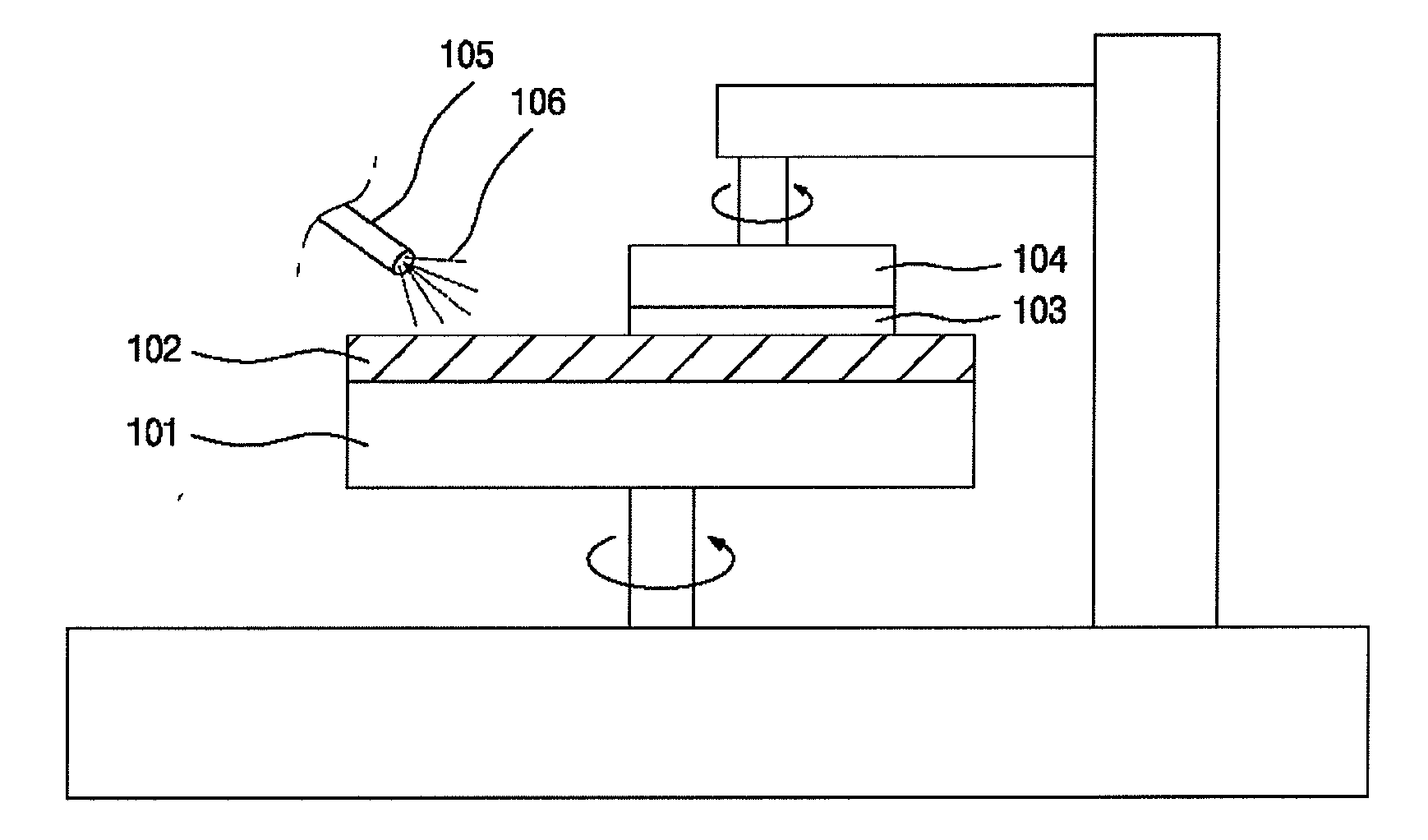
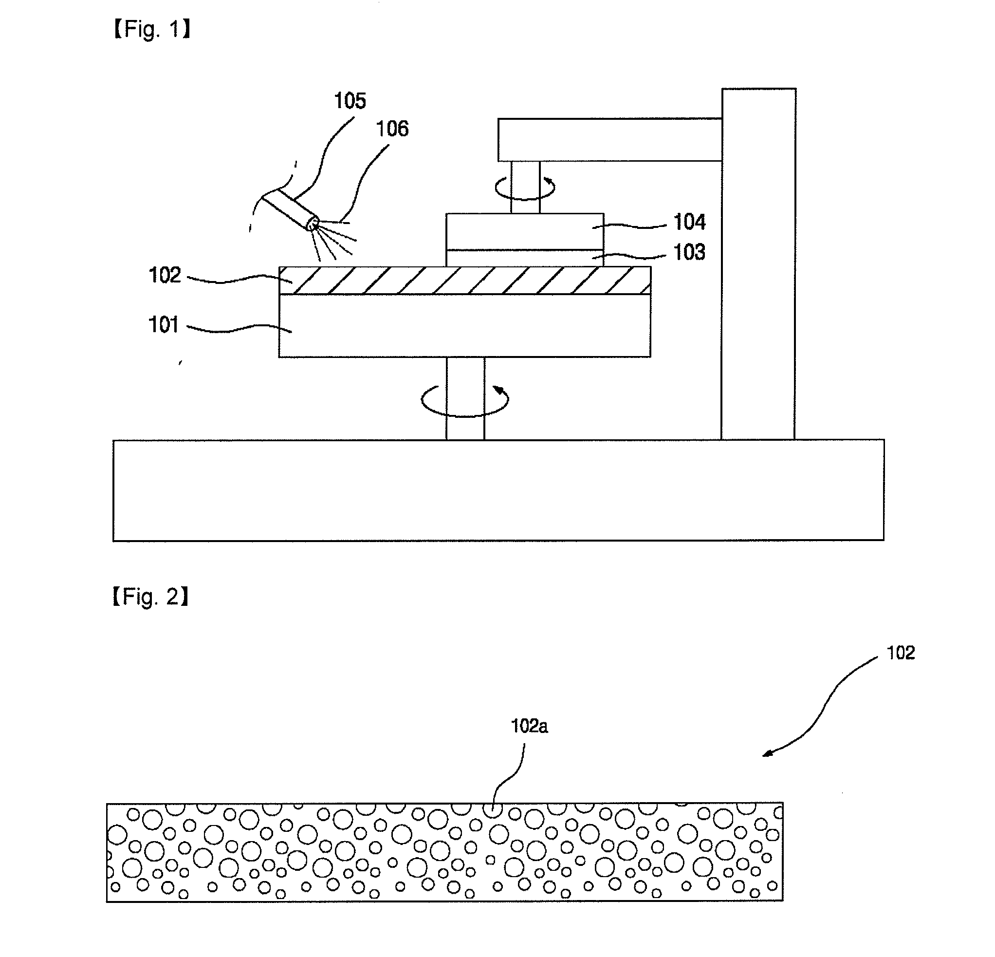
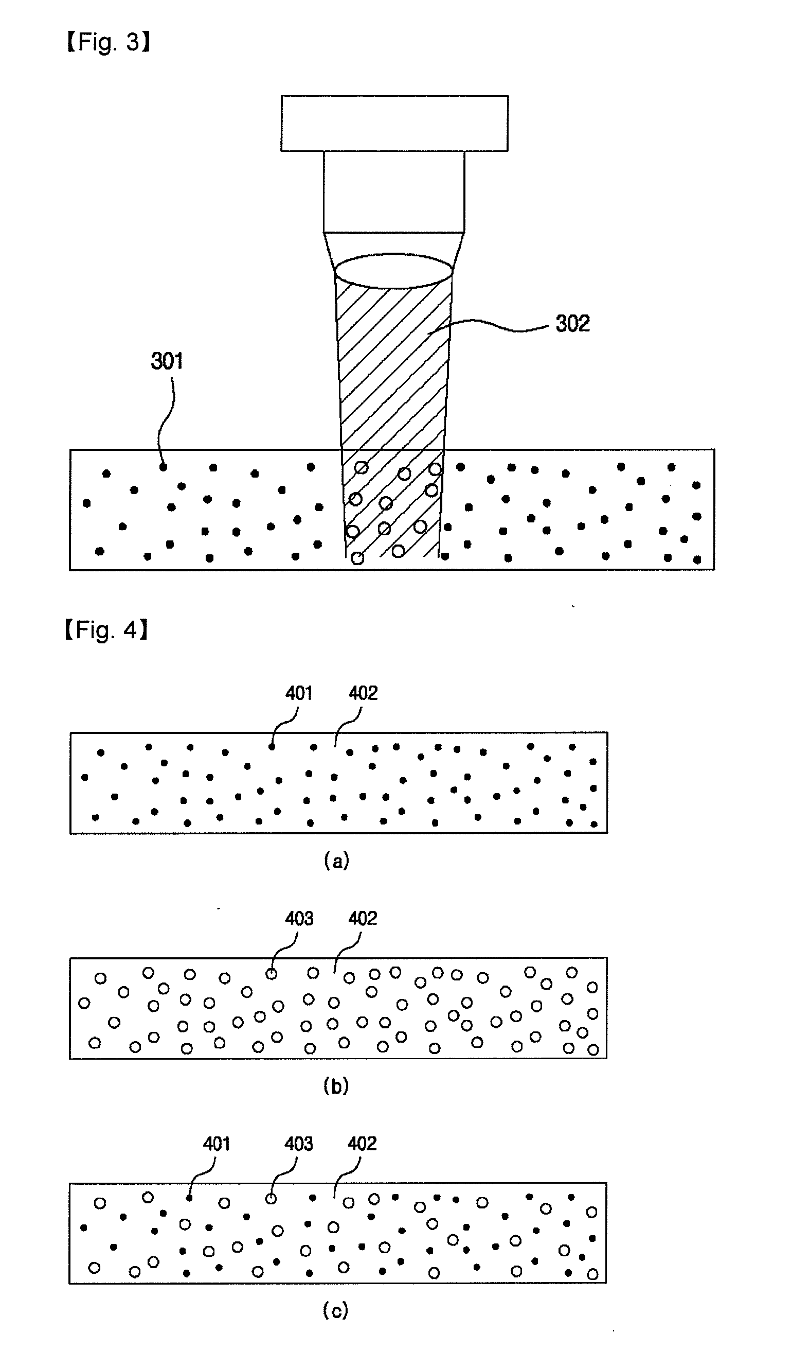
[0024]The CMP polishing pad disclosed herein uses light-absorbing materials having a controlled size and the light-absorbing materials are dispersed in the CMP polishing pad. The CMP polishing pad has pores formed by breakdown of the light-absorbing material through the control of the intensity of laser beams. Thus, it is possible to freely control the size of pores formed in the CMP polishing pad. F

Problems solved by technology

When the formation of patterns is repeated in a layered structure, a level difference gradually becomes severe at the top of the resultant structure.
Such a severe level difference at the top of the structure makes the focus of a photomask pattern unclear in the subsequent photolithography process, thereby making it difficult to form a fine pattern.
However, it is difficult to allow the micro-sized

Method used


Image

  • Cmp polishing pad having pores formed therein, and method for manufacturing same
  • Cmp polishing pad having pores formed therein, and method for manufacturing same
  • Cmp polishing pad having pores formed therein, and method for manufacturing same

Examples


Example

BEST MODE

[0032]Hereinafter, the embodiments of the present disclosure will be described in detail with reference to accompanying drawings.

[0033]The CMP polishing pad disclosed herein includes light-absorbing materials for forming pores, wherein the light-absorbing materials are dispersed in the CMP polishing pad, pores are formed by breakdown of the light-absorbing materials that have absorbed laser beams irradiated to the polishing pad, and sizes of the pores are determined by the intensity of the laser beams or the size of the light-absorbing materials.

[0034]The pores formed in the CMP polishing pad are obtained by the light-absorbing materials dispersed in the polishing pad and laser beams. The light-absorbing materials absorb the laser beams and undergo an increase in temperature by themselves, resulting in instant vaporization. Otherwise, such an increase in temperature causes instant vaporization of the surrounding polymer material to assist formation of pores. Such a micro...


PUM

PropertyMeasurementUnit
Diameteraaaaaaaaaa
Diameteraaaaaaaaaa
Pore sizeaaaaaaaaaa

Abstract

The present invention relates to a CMP polishing pad and to a method for manufacturing same, characterized in that a light-absorbing material for forming pores is dispersed in the pad. Pores formed in the CMP polishing pad of the present invention are formed by means of the breakdown of the light-absorbing material which absorbs a laser beam irradiated on the polishing pad, enabling the pore size to be controlled by controlling the amount of the light-absorbing material, the intensity of the laser beam, etc., and enabling pore distribution to be freely controlled through the computer numerical control (CNC) technique. Accordingly, a CMP polishing pad can be provided that exhibits the highest polishing effectiveness in accordance with the material to be polished or the type of slurry.

Description

TECHNICAL FIELD[0001]The present disclosure relates to a Chemical Mechanical Polishing (CMP) polishing pad and a method for manufacturing the same, and more particularly, to a CMP polishing pad having pores formed therein in order to inhibit leakage of slurry, thereby improving the stability of a CMP process and a method for manufacturing the same.BACKGROUND ART [0002]Semiconductors are devices obtained by high-density integration of electronic devices such as transistors or capacitors on a semiconductor substrate such as silicon, and are fabricated by using deposition, photolithography and etching technologies. Repetition of such deposition, photolithography and etching processes results in formation of a pattern having a specific shape. When the formation of patterns is repeated in a layered structure, a level difference gradually becomes severe at the top of the resultant structure. Such a severe level difference at the top of the structure makes the focus of a photomask pattern ...

Claims


Application Information

Patent Timeline
IPC IPC(8): B24D11/00B29C67/20
CPCB24D18/00B24B37/26H01L21/304
Inventor KIM, CHIL MIN
Owner IND UNIV COOP FOUND SOGANG UNIV
Learn More