Method and system for transmitting muti-carrier uplink data at network-side

Active Publication Date: 2012-07-05
ZTE CORP
View PDF5 Cites 21 Cited by
  • Summary
  • Abstract
  • Description
  • Claims
  • Application Information

AI Technical Summary

Benefits of technology

[0046]Considering all possible scenes, the present invention provides a method for transmitting and receiving multi-carrier enhanced dedicated channel uplink data frames between a NodeB, drift radio network controller and serving radio network controller at a network side such that in the process where carrier identifier information corresponding to a carrier of a multi-carrier enhanced dedicated channel cell in multiple carriers is notified when the multi-carrier enhanced dedicated channel cell is set up or added and the carrier identifier information is applied to setting, transmitting and receiving of the enhanced dedicated channel uplink data frames, the carriers from which data carried in the enhanced dedicated channel uplink data frames is received can be correctly identified and distinguished, so as to ensure the availability of the multi-carrier high-speed uplink packet access technology.
[0047]With the method in accordance with the present invention, the problem of confusing the received data from different carriers can be avoided such that the radio network controller of an aggregation party can clearly distinguish the data from various carriers to ensure normal transmission of actual service data of the terminal, avoid offline, and ensure the availability of the dual-carrier high-speed uplink packet access technology.

Problems solved by technology

Once the received data from different carriers are confused, the serving radio network controller can not distinguish the data, and can not normally reorder the data and perform micro-diversity combination, and all data is erroneous, resulting in unavailability of actual services and final offline of the terminal.
Thus, the problem that a serving radio network controller can not determine whether the data carried in the enhanced dedicated channel uplink data frame is from the primary carrier or the secondary carrier will occur in the existing technology.
The radio network controller can not determine the source of the data, and thus can not normally reorder the data and perform micro-diversity combination, and all data is discarded erroneously, resulting in unavailability of actual services and final offline.
It also means that the existing multi-carrier high-speed uplink packet access technologies are unavailable.

Method used


Image

  • Method and system for transmitting muti-carrier uplink data at network-side
  • Method and system for transmitting muti-carrier uplink data at network-side
  • Method and system for transmitting muti-carrier uplink data at network-side

Examples


first embodiment

The First Embodiment

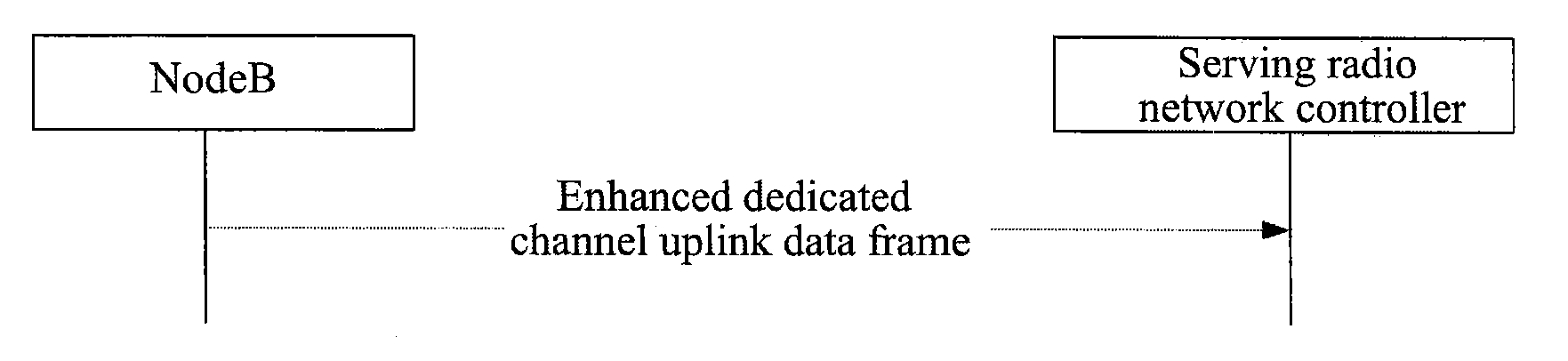
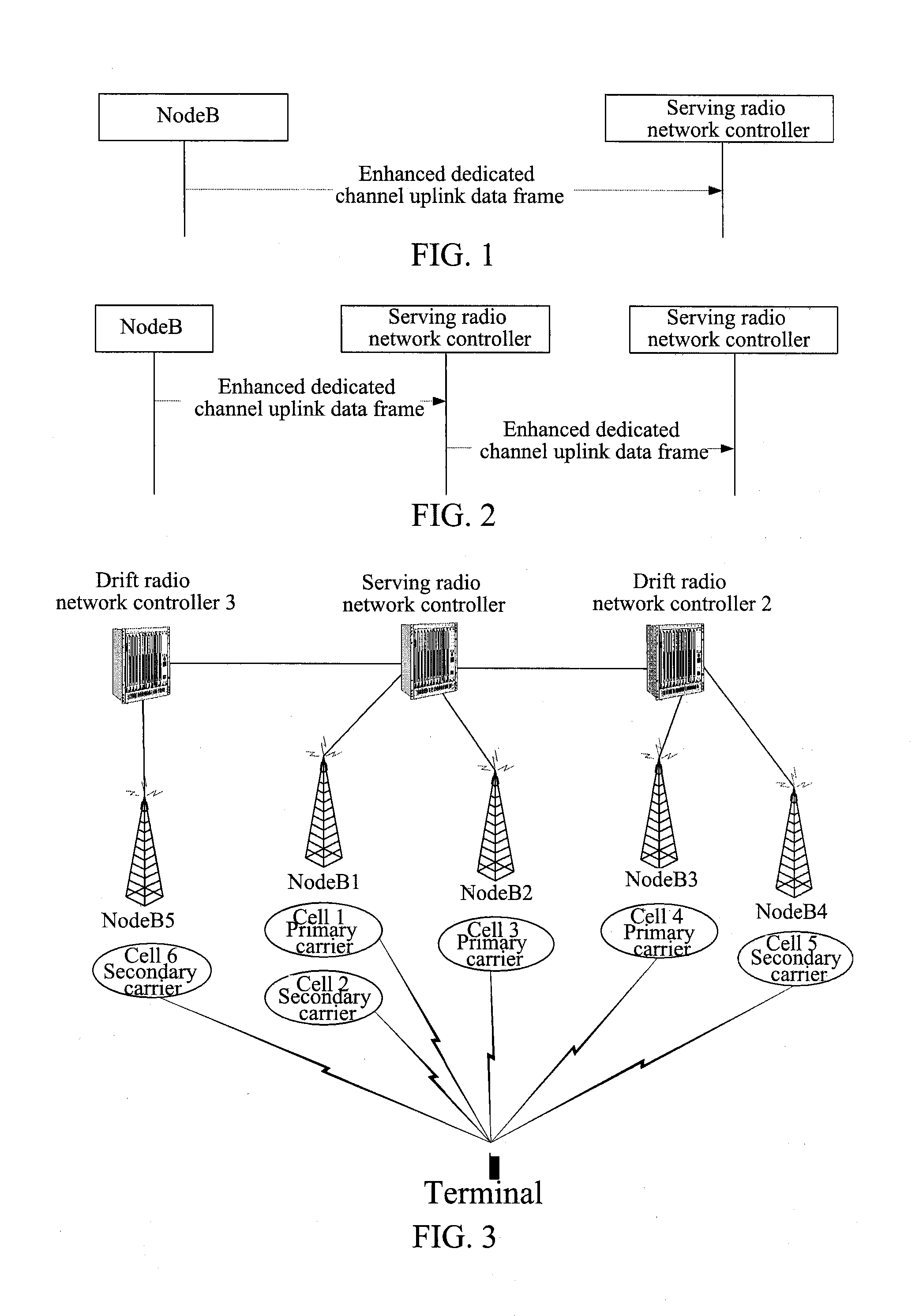
[0079]The present embodiment describes a method for transmitting and receiving dual-carrier enhanced dedicated channel uplink data frames between NodeB 1 and radio network controller 1. NodeB 1 belongs to radio network controller 1. The processing procedure of the first embodiment is shown in FIG. 5, and each of its steps is described as follows.

[0080]In step 110, for a terminal using the dual-carrier high-speed uplink packet access technology, radio network controller 1 sets up a dual-carrier enhanced dedicated channel cell (that is, a cell using the enhanced dedicated channel in an uplink direction of one carrier in the two carriers), cell 1, through a radio link setup process in NodeB 1, and notifies NodeB 1 of a carrier identifier corresponding to the carrier of the dual-carrier enhanced dedicated channel cell in the multiple carriers. The carrier identifier corresponding to the carrier of cell 1 in the two carriers is the primary carrier.

[0081]In step 120, f...

second embodiment

The Second Embodiment

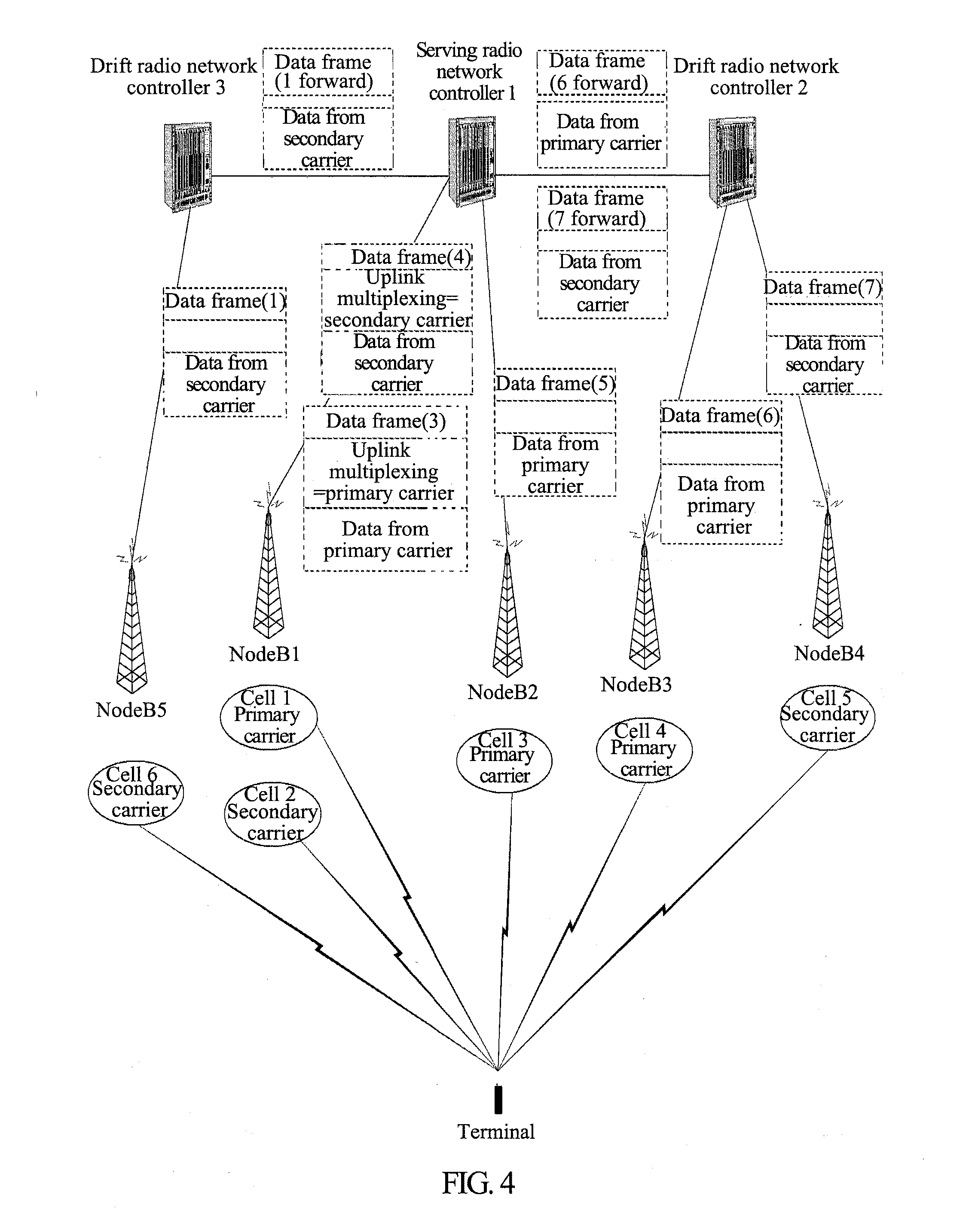
[0088]The present embodiment describes a method for transmitting and receiving dual-carrier enhanced dedicated channel uplink data frames between NodeB 5 and radio network controller 1 (serving radio network controller) via radio network controller 3 (drift radio network controller). NodeB 5 belongs to radio network controller 3 (drift radio network controller). The processing procedure of the second embodiment is shown in FIG. 6, and each of its steps is described as follows.

[0089]In step 210, for a terminal using the dual-carrier high-speed uplink packet access technology, radio network controller 1 sets up a dual-carrier enhanced dedicated channel cell (that is, a cell using the enhanced dedicated channel in an uplink direction of one carrier in the two carriers), cell 6, through a radio link setup process in radio network controller 3, and notifies radio network controller 3 of a carrier identifier corresponding to the carrier of the dual-carrier enhanced de...

third embodiment

The Third Embodiment

[0095]The present embodiment describes a method for transmitting and receiving a dual-carrier enhanced dedicated channel uplink data frame between NodeB 3 and NodeB 4 and radio network controller 1 (serving radio network controller) via radio network controller 2 (drift radio network controller). NodeB 3 and NodeB 4 belong to radio network controller 2 (drift radio network controller). The processing procedure of the third embodiment is shown in FIG. 7, and each of its steps is described as follows.

[0096]In step 310, for a terminal using the dual-carrier high-speed uplink packet access technology, radio network controller 1 sets up a dual-carrier enhanced dedicated channel cell (that is, a cell using the enhanced dedicated channel in an uplink direction of one carrier in the two carriers), cell 5, through a radio link setup process in radio network controller 2, and notifies radio network controller 2 of a carrier identifier corresponding to the carrier of the du...


PUM


Abstract

The present invention discloses a method and system for transmitting multi-carrier uplink data at a network side. The method comprises: whenever setting up or adding a multi-carrier enhanced dedicated channel cell, a radio network controller notifying a NodeB dominating the multi-carrier enhanced dedicated channel cell of carrier identifier information of a carrier corresponding to the multi-carrier enhanced dedicated channel cell; and whenever receiving data transmitted by a terminal using a multi-carrier high-speed uplink packet access technique in the multi-carrier enhanced dedicated channel cell via the carrier, the NodeB carrying the carrier identifier information of the carrier bearing the data in enhanced dedicated channel uplink data frames when constructing the enhanced dedicated channel uplink data frames, and transmitting the constructed enhanced dedicated channel uplink data frames to the radio network controller. The present invention can avoid the problem of confusion of the received data from different carriers.

Description

TECHNICAL FIELD[0001]The present invention relates to a wireless communication system, and in particular, to a method and system for transmitting multi-carrier enhanced dedicated channel uplink data at a network side.BACKGROUND OF THE RELATED ART[0002]In wireless communication systems, the Interconnection of type B (IUB for short hereinafter) interface is a logic interface between a Radio Network Controller (RNC for short) and a NodeB. The Interconnection of RNC (IUR) interface, which is an interface used by the radio network controller to exchange signaling and data with other radio network controllers, is the tie of interconnection between radio network subsystems.[0003]When a terminal sets up a connection to a radio access network and generates soft handover at the IUR interface, resources of more than one radio network controller will be used, and different radio network controllers will function as different roles at this point.[0004]A Serving Radio Network Controller (SRNC for...

Claims


Application Information

Patent Timeline
IPC IPC(8): H04W72/04
CPCH04L5/0098H04W72/0433H04W72/29
Inventor CHENG, XIANGLIU, LINKE, YAZHU
Owner ZTE CORP
Why Eureka
Try Eureka