
Anti-vibration tube support plate arrangement for steam generators

a technology of anti-vibration and tube support, which is applied in the direction of lighting and heating apparatus, greenhouse gas reduction, nuclear elements, etc., can solve the problems of tube wall wear and breach of the pressure barrier between the primary and secondary fluid system, and achieve the effect of reducing tube vibration

Active Publication Date: 2012-07-05
WESTINGHOUSE ELECTRIC CORP
View PDF46 Cites 10 Cited by
  • Summary
  • Abstract
  • Description
  • Claims
  • Application Information

AI Technical Summary

Benefits of technology

[0010]These and other objectives are achieved in accordance with this invention by providing a tube and shell steam generator having a primary side for circulating a heated fluid and a secondary side having an axial dimension, for circulating a fluid to be heated by the heated fluid circulating in the primary side. The steam generator includes a channel head for receiving the heated fluid and a tube sheet that separates the channel head from the secondary side. A plurality of heat exchanger tubes respectively extend from the channel head, through the tube sheet and through a portion of the secondary side. A plurality of axially spaced tube support plates are supported in the secondary side approximately perpendicular to the tube axis and have through holes that respectively surround at least some of the heat exchanger tubes extending into the secondary side and through which the corresponding heat exchanger tubes pass, with the holes surrounding each heat exchanger tube, of at least some of the heat exchanger tubes, substantially axially aligned when the steam generator is in a cold condition. A displacement means is provided for laterally offsetting at least one of the tube support plates from one other of the tube support plates when the steam generator is in a hot condition to place a lateral load on the corresponding heat exchanger tubes sufficient to prevent liftoff and, thus, restrain vibration of the tubes.

Problems solved by technology

It is, therefore, important that the U-tubes be maintained defect free so that no breaks will occur in the U-tubes that will cause radioactive materials from the primary fluid to enter the secondary side; an undesirable result.
Vibration due to fluidelastic excitation of the heat exchanger tubes can result in wear of the walls of the tubes and breach of the pressure barrier between the primary and secondary fluid systems at the locations where the heat exchanger tubes pass through holes in support plates which are axially spaced along the tube bundle to support the tubes.
This is especially a problem in axial flow preheaters, that employ a partition plate to separate the secondary side flow into hot leg and cold leg sides to minimize mixing of the warmer recirculating water with the cooler feedwater.

Method used


Image

  • Anti-vibration tube support plate arrangement for steam generators
  • Anti-vibration tube support plate arrangement for steam generators
  • Anti-vibration tube support plate arrangement for steam generators

Examples


Embodiment Construction

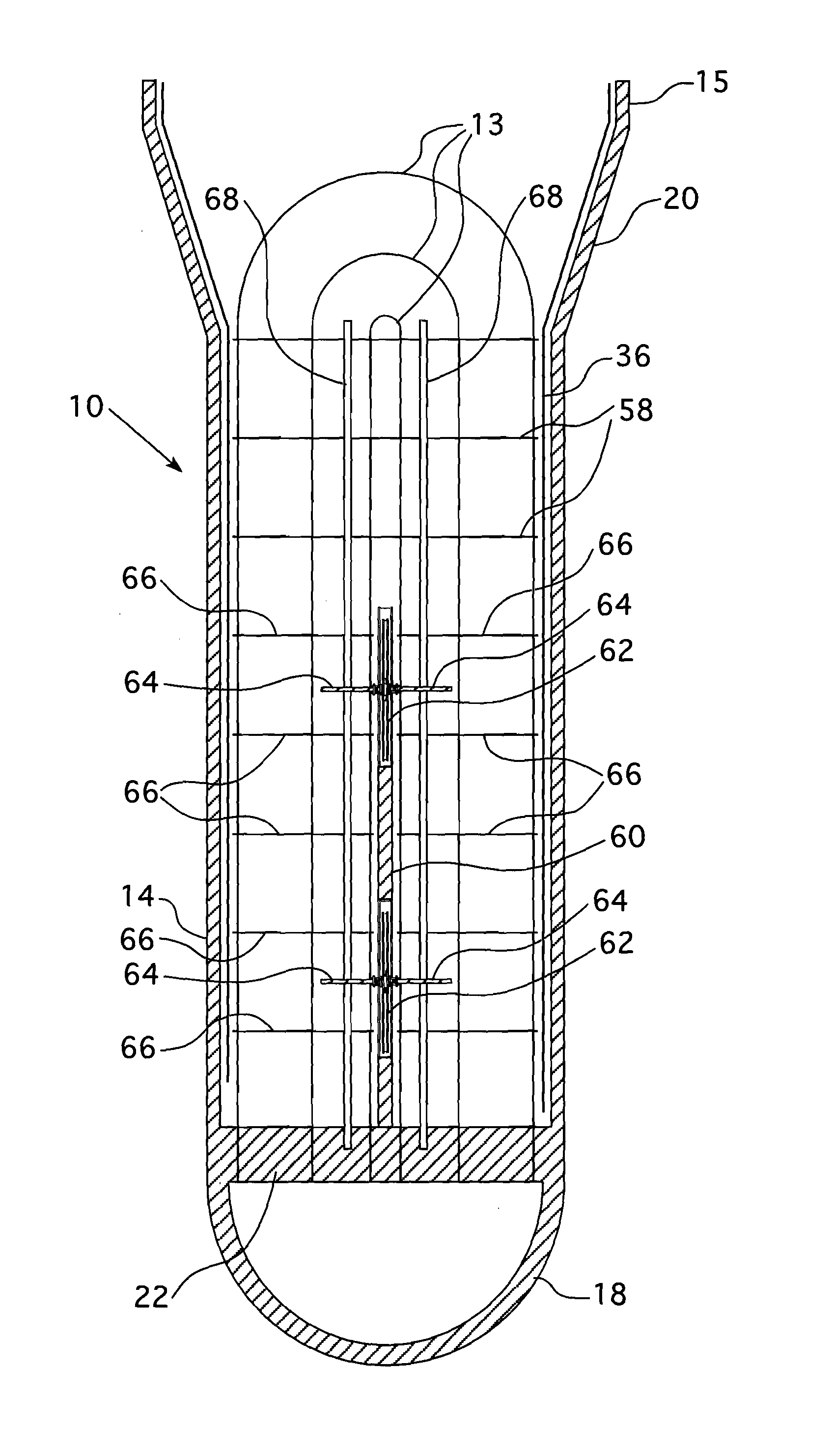
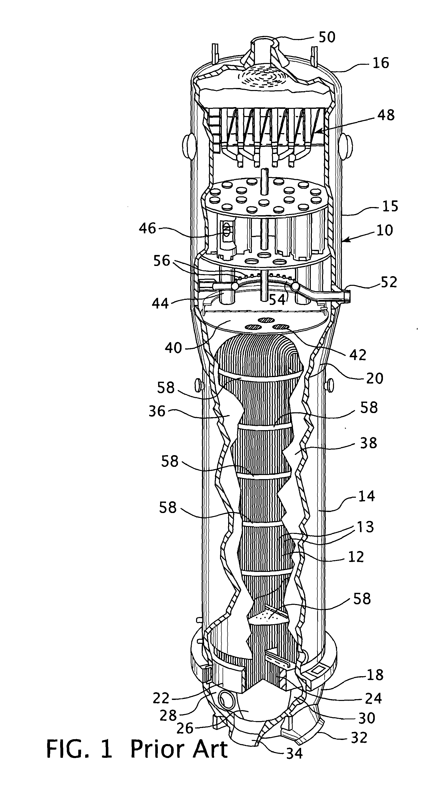
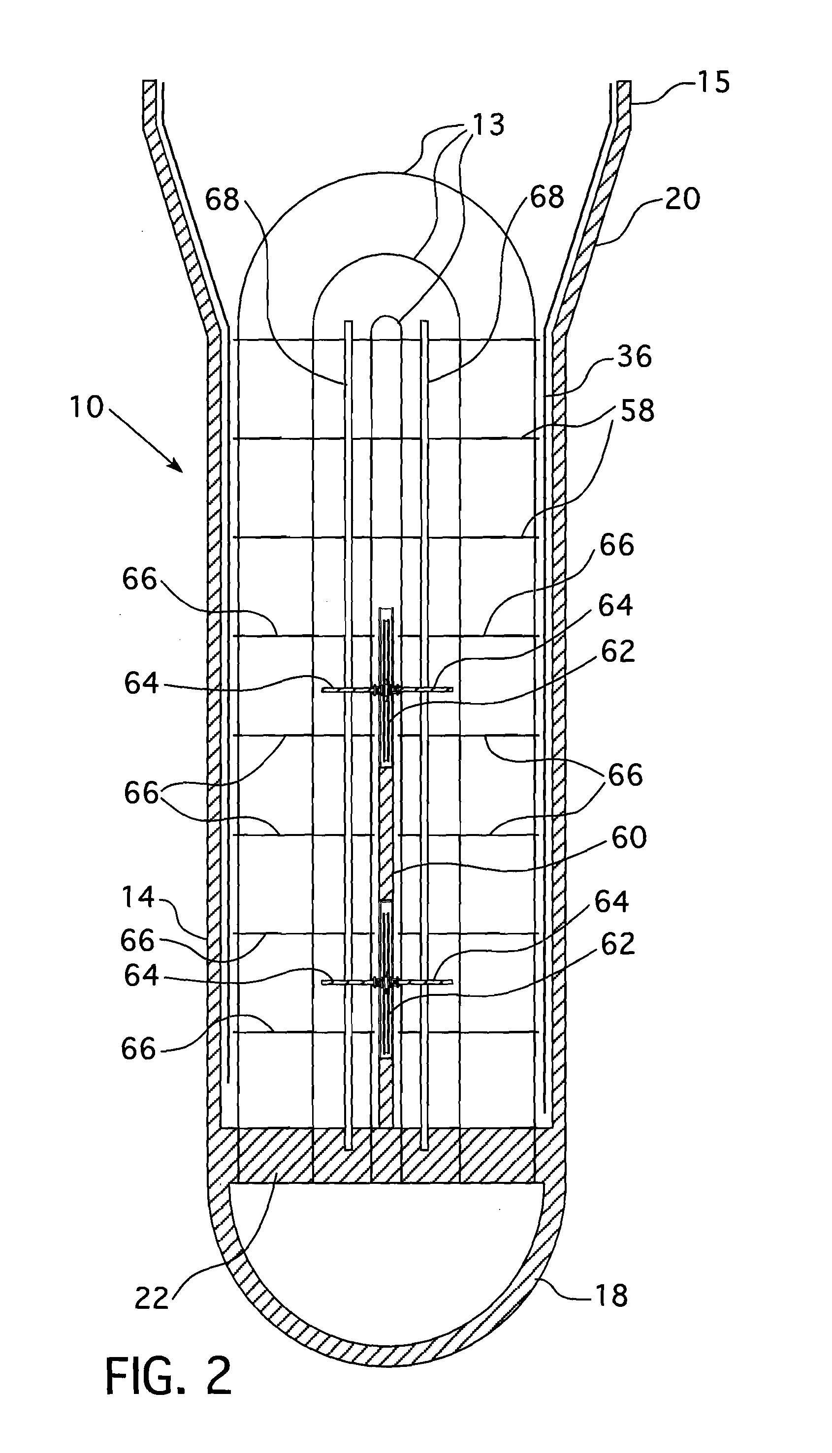
[0026]Referring now to the drawings, FIG. 1 shows a steam or vapor generator 10 that utilizes a plurality of U-shaped tubes which form a tube bundle 12 to provide the heating surface required to transfer heat from the primary fluid to vaporize or boil the secondary fluid. The steam generator 10 comprises a vessel having a vertically oriented tubular shell portion 14 and a top enclosure or dished head 16 enclosing the upper end and a generally hemispherical-shaped channel head 18 enclosing the lower end. The lower shell portion 14 is smaller in diameter than the upper shell portion 15 and a frustoconical-shaped transition 20 connects the upper and lower portions. A tube sheet 22 is attached to the channel head 18 and has a plurality of holes 24 disposed therein to receive ends of the U-shaped tubes 13. A dividing plate 26 is centrally disposed within the channel head 18 to divide the channel head into two compartments 28 and 30, which serve as headers for the tube bundle 12. Compartm...


PUM


Abstract

A means of offsetting semi-circular tube support plates typically present in heat exchangers with cross flow baffles, such as axial flow economizers, utilizing the motive force of steam generator pressurization. The offset slightly flexes the tubes, thereby providing a preload which minimizes the potential for tube vibration and wear.

Description

BACKGROUND OF THE INVENTION[0001]1. Field of the Invention[0002]This invention relates generally to tube support arrangements for steam generators and more particularly to a tube support arrangement for a tube and shell steam generator that imparts a preload on the tubes.[0003]2. Description of Related Art[0004]A pressurized water nuclear reactor steam generator typically comprises a vertically oriented shell, a plurality of U-shaped tubes disposed in the shell so as to form a tube bundle, a tube sheet for supporting the tubes at the ends opposite the U-like curvature, a dividing plate that cooperates with the tube sheet and a channel head forming a primary fluid inlet header at one end of the tube bundle and a primary fluid outlet header at the other end of the tube bundle. A primary fluid inlet nozzle is in fluid communication with the primary fluid inlet header and a primary fluid outlet nozzle is in fluid communication with a primary fluid outlet header. The steam generator seco...

Claims


Application Information

Patent Timeline
IPC IPC(8): F22B37/20G21C15/02F28F9/013
CPCF22B1/025F22B37/206Y02E30/40F28F9/0131G21D1/00F22B37/002F22B37/205F22B37/66Y02E30/00Y02E30/30F22B37/20F28F9/013G21C15/02
Inventor WEPFER, ROBERT M.PRABHU, PADMANABHA J.
Owner WESTINGHOUSE ELECTRIC CORP
Learn More