Medical ultrasound device with force detection

Active Publication Date: 2012-06-28
KONINKLIJKE PHILIPS ELECTRONICS NV
View PDF3 Cites 20 Cited by
  • Summary
  • Abstract
  • Description
  • Claims
  • Application Information

AI Technical Summary

Benefits of technology

[0006]It would be advantageous to achieve a force sensor suitable for integration into a medical device, such as a medical probe or catheter, which does not require additional space, or only infers minimal space requirements in the distal end region of the medical device. In general, the invention preferably seeks to mitigate, alleviate or eliminate one or more of the above mentioned disadvantages singly or in any combination. In particular, it may be seen as an object of the present invention to provide a method that solves the above mentioned problems, or other problems, of the prior art.
[0012]The invention provides a medical device, such as a catheter or probe, with integrated ultrasound facilities, where the ultrasound radiation can be used for general purposes, as well as for generating a measure of the contact force imposed to the distal end region. In an advantageous embodiment, the one or more ultrasound transducers are capable of generating acoustic radiation suitable for monitoring a region of interest simultaneously with, concurrently with or together with detecting the acoustic path length between the ultrasound transducer and the transmission element. The contact force imposed to the distal end is deduced from the path length. By basing the detection of the contact force on ultrasound radiation and path length detection between the ultrasound transducer and the transmission element, key elements to perform the contact force detection are elements which also may be used for other purposes, and a separate sensor is not needed. The ultrasound transducer(s) may be used for monitoring purposes and a transmission element is always needed in order to couple the acoustic radiation out of the medical device. A compact and cost-effective medical device is therefore provided.
[0016]In an advantageous embodiment, the medical device further comprises a compressive element positioned in the distal end region, the compressive element being capable of varying its size as a function of an exerted compression force resulting in acoustic path length variations. It is an advantage to use a compressive element since a compressive element can be incorporated into the distal end region in a compact way. Depending on the specific embodiment, a compressive element can be incorporated into the distal end region in a way which does not require additional space in the distal end region, or which only imposes minimal space requirements.
[0022]In an embodiment where the transmission element further comprises a treatment modality for treatment of body tissue, the treatment modality may be operatively connected to the controller unit, so that the treatment modality is controllable to operate within a pre-specified contact force range. The relevant contact forces may be so small that the medical practitioner is unable to perceive changes in imposed contact force, controlling the treatment modality to operate within a pre-specified contact force range may ensure that the ablative power delivered to the tissue may safely by applied.

Problems solved by technology

Too great a contact force may lead to unnecessary damage of healthy tissue, whereas too low a contact force may lead to the creation of incomplete lesions.
Moreover, the risk of complications increases dramatically with contact force, in particular with respect to the risk of causing stream pops and thrombus in connection with the ablation.
Additionally by applying a too high contact force, the cardiac wall may be affected in a way which leads to electro-anatomic mapping registration errors, cf.
The tri-axial force sensor and associated fibers take up space in the distal region of the catheter, moreover a light source is required which adds to the cost of the device.

Method used


Image

  • Medical ultrasound device with force detection
  • Medical ultrasound device with force detection
  • Medical ultrasound device with force detection

Examples


Embodiment Construction

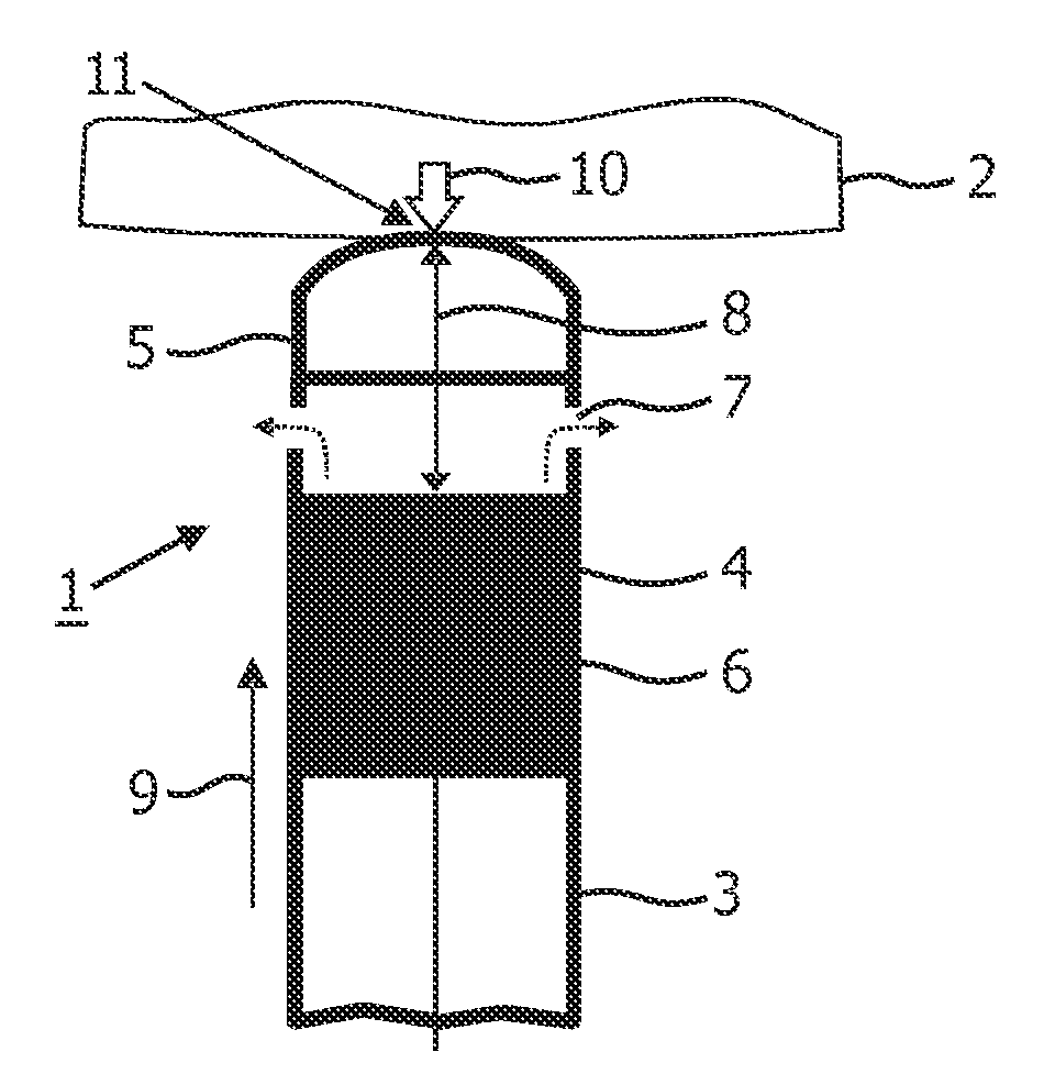
[0042]The present invention is disclosed in connection with a RF ablation catheter comprising a monitoring system in accordance with embodiments of the present invention. It is however to be understood that, while such an application is advantageous, the invention is not limited to this. In fact, the medical device may be applied in connection with any device which uses ultrasound transducers and which supports a structural configuration which enables that an acoustic path length between a transmission element and the ultrasound transducer varies with contact force imposed to the distal end region.

[0043]FIG. 1 schematically illustrates the distal end region 1 of an ablation catheter-based probe, hereafter simply referred to as a catheter, abutting an object 2, such as tissue in the form of a cardiac wall. The catheter comprises an elongated body 3, a distal end region 1 and a proximal end (not shown). A length axis 9 runs along the elongation of the elongated body. The distal end re...


PUM


Abstract

A medical ultrasound device is disclosed. The device comprises an elongated body having a proximal end and a distal end region (1). One or more ultrasound transducers (4) for generating acoustic radiation are positioned in the distal end region, inside the elongated body. A transmission element (5) which is substantially transparent to acoustic radiation is positioned in the radiation path of the acoustic radiation, and a controller unit is operatively connected to the ultrasound transducer. The transmission element and the one or more ultrasound transducers are mounted so that an acoustic path length (8) between the transmission element (5) and the ultrasound transducer (4) varies with contact force (10) imposed to the distal end region. The controller unit detects the acoustic path length between the ultrasound transducer and the transmission element and determines the contact force from the detected acoustic path length. In an embodiment, the medical device is an ultrasound RF ablation catheter.

Description

FIELD OF THE INVENTION[0001]The invention relates to a medical ultrasound device, such as a probe or catheter-based device. In particular the invention relates to such devices capable of detecting the contact force imposed to the distal end region of the device.BACKGROUND OF THE INVENTION[0002]Catheter-based surgery is advantageously used in various connections to treat body organs with minimal incision size and clearance of the organs. As an example, cardiac arrhythmias may be treated by various catheter-based ablation techniques to destroy arrhythmogenic parts of the cardiac tissue. Specifically, radio-frequency (RF) ablation, high intensity focused ultrasound (HIFU) or cryo-ablations of the tissue are commonly used.[0003]In connection with the ablation process of cardiac tissue, it has recently been realized that the contact force between an ablation catheter's tip and the cardiac tissue is a highly important variable that must be controlled. It has been shown that the contact fo...

Claims


Application Information

Patent Timeline
IPC IPC(8): A61B8/12A61B18/14A61N7/00
CPCA61B5/6885A61B8/12A61B18/0206A61B18/12A61B8/445A61B19/46A61B2017/00106A61B2019/465A61B18/1492
Inventor BARLEY, MAYA ELLAHARKS, GODEFRIDUS ANTONIUSDELADI, SZABOLCS
Owner KONINKLIJKE PHILIPS ELECTRONICS NV
Why Eureka
Try Eureka