
Pneumatic tire

a technology of pneumatic tires and ribs, which is applied in the direction of non-skid devices, vehicle components, transportation and packaging, etc., can solve the problems of shoulder ribs and the need to suppress uneven wear, and achieve the effect of ensuring the functionality of the narrow rib 5

Active Publication Date: 2012-06-28
YOKOHAMA RUBBER CO LTD
View PDF7 Cites 4 Cited by
  • Summary
  • Abstract
  • Description
  • Claims
  • Application Information

AI Technical Summary

Benefits of technology

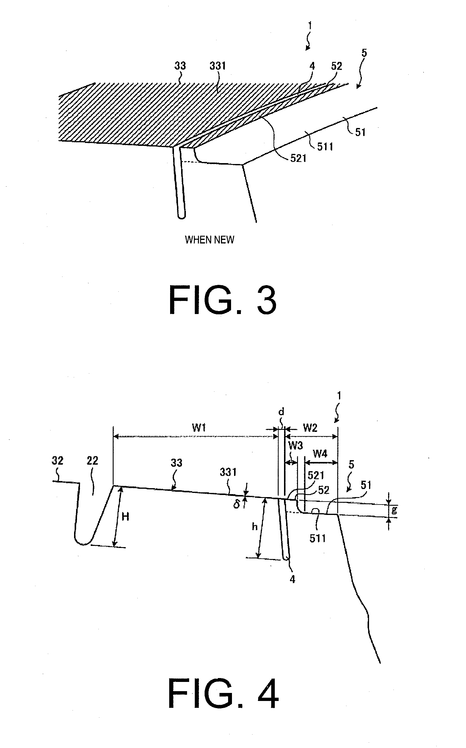
[0006]The present technology provides a pneumatic tire by which uneven wear of a shoulder rib can be suppressed. A pneumatic tire according to the present technology includes a plurality of circumferential main grooves extending in a tire circumferential direction, a plurality of land portions partitioned by the circumferential main grooves, a narrow groove extending in the tire circumferential direction and disposed in an edge portion of a road contact surface side and an outer side in the tire width direction of the land portion on an outermost side in a tire width direction (hereinafter referred to as the “shoulder land portion”), and a narrow rib that is partitioned by the narrow groove. The narrow rib includes an offset portion having a road contact surface offset inward in a tire radial direction from the road contact surface of the shoulder land portion, and a protrusion protruding in the tire radial direction from the offset portion, extending in the tire circumferential direction, and having a top surface that is substantially flush with a profile line of the shoulder land portion.
[0012]With the pneumatic tire according to the present technology, the protrusion of the narrow rib contacts the ground under conditions when the tire is new and where the road contact surface of the shoulder land portion contacts the ground. Thus, the protrusion functions as a wear sacrifice rib and the functionality of the narrow rib is ensured. This leads to the advantage that uneven wear of the shoulder land portion at the initial period of wear is suppressed from when the tire is new.

Problems solved by technology

Pneumatic tires applied to pneumatic radial tires for heavy loads and the like have a problem in that there is a need to suppress uneven wear (e.g. step wear) of the shoulder rib.

Method used


Image

  • Pneumatic tire
  • Pneumatic tire
  • Pneumatic tire

Examples


examples

[0052]FIGS. 9-10 are tables showing the results of performance testing of pneumatic tires according to embodiments of the present technology. In the examples, uneven wear resistance performance tests were performed on a plurality of varying pneumatic tires.

[0053]In the performance tests, pneumatic tires with a tire size of 295 / 75R22.5 were assembled on TRA defined standard rims; and a prescribed air pressure and load defined by TRA were applied to these pneumatic tires. Additionally, the pneumatic tires were mounted on the steering axle of a North American Class 8 2-DD test vehicle. Next, this test vehicle was driven for 100,000 miles (about 160,000 km) and, thereafter, area and depth of uneven wear that occurred in the shoulder land portion was measured. The index value of the pneumatic tire of the Conventional Example was set as the standard score (100) and an indexed evaluation based on these measurement results was performed. With this evaluation, larger numbers are more prefera...


PUM


Abstract

A pneumatic tire including a plurality of circumferential main grooves extending in a tire circumferential direction, a plurality of land portions partitioned by the circumferential main grooves, a narrow groove extending in the tire circumferential direction and disposed in an edge portion of a road contact surface side and an outer side in the tire width direction of the shoulder land portion on an outermost side in a tire width direction, and a narrow rib that is partitioned by the narrow groove. The narrow rib includes an offset portion having a road contact surface offset inward in a tire radial direction from the road contact surface of the shoulder land portion, and a protrusion protruding in the tire radial direction from the offset portion, extending in the tire circumferential direction, and having a top surface that is substantially flush with a profile line of the shoulder land portion.

Description

PRIORITY CLAIM[0001]Priority is claimed to Japan Patent Application Serial No. 2010-291086 filed on Dec. 27, 2010 and Japan Patent Application Serial No. 2011-220458 filed on Oct. 4, 2011.BACKGROUND[0002]1. Technical Field[0003]The present technology relates to a pneumatic tire, and more specifically, to a pneumatic tire whereby uneven wear of a shoulder rib can be suppressed.[0004]2. Related Art[0005]Pneumatic tires applied to pneumatic radial tires for heavy loads and the like have a problem in that there is a need to suppress uneven wear (e.g. step wear) of the shoulder rib. Therefore, conventional pneumatic tires include narrow grooves extending in a tire circumferential direction along an edge portion on an outer side in the tire width direction of the shoulder rib, and narrow ribs that are partitioned by the narrow grooves. The narrow ribs are so-called “wear sacrifice ribs”, and inhibit uneven wear of the shoulder rib by proactively being worn when the tire is rolling. The te...

Claims


Application Information

Patent Timeline
Patent Type & Authority Applications(United States)
IPC IPC(8): B60C11/03B60C11/117
CPCB60C11/04B60C2011/013B60C11/01B60C2011/0348B60C2011/0355
Inventor OKABE, HIDETOSHI
Owner YOKOHAMA RUBBER CO LTD
Learn More