Ion mobility spectrometer

a spectrometer and mobility technology, applied in the field of ion mobility spectrometers, can solve the problems of reducing the rate at which the measurement of the ion mobility spectrum can be performed per one second, sensitivity to deterioration, and limiting the shutter open time, so as to shorten the time interval of measurement, increase the frequency, and solve the effect of high resolution power

Inactive Publication Date: 2018-11-15
SHIMADZU CORP
View PDF2 Cites 2 Cited by
  • Summary
  • Abstract
  • Description
  • Claims
  • Application Information

AI Technical Summary

Benefits of technology

The present invention provides an ion mobility spectrometer that can measure ions with high resolving power in either a slow or a fast mode. The device can also detect molecules with identical mass but different structures and can obtain an ion mobility spectrum with high resolving power even at high sampling rates. This enables more accurate analysis of samples and reduces the likelihood of missed components or distortion of peak shape.

Problems solved by technology

However, shortening the shutter open time decreases the amount of ions passing through the shutter and causes the sensitivity to deteriorate.
Thus, there is a limit in shortening the shutter open time if a certain level of sensitivity is demanded.
In other words, an operation period of the shutter gate becomes longer, which results in a decrease in the rate at which the measurement for the ion mobility spectrum can be performed per one second (sampling rate).
In a case where the ion mobility spectrometer is used as a detector of a liquid chromatograph (LC) to analyze components in a sample which are sequentially eluted from a column of the LC, a decrease in the sampling rate results in a longer time interval between data points in the chromatogram.
This may possibly prevent a peak from being appropriately captured.

Method used


Image

  • Ion mobility spectrometer
  • Ion mobility spectrometer
  • Ion mobility spectrometer

Examples


Embodiment Construction

[0031]An embodiment of the ion mobility spectrometer according to the present invention is described as follows, with reference to the attached drawings.

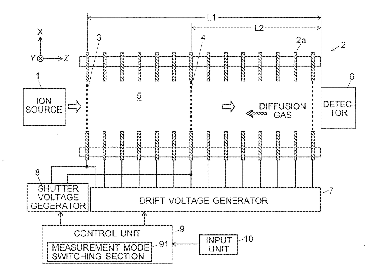
[0032]FIG. 1 is a schematic sectional diagram showing an ion mobility spectrometer according to the present embodiment. Components which are identical or corresponding to those included in a conventional ion mobility spectrometer already described with reference to FIG. 5 are denoted by the same reference signs as those used for the conventional ion mobility spectrometer.

[0033]The ion mobility spectrometer according to the present embodiment includes: a first shutter gate 3 disposed at an entrance of a drift region 5; and a second shutter gate 4 disposed in the drift region 5 on the downstream side of the shutter gate 3 in the ion-drifting direction. A drift voltage generator 7 applies predetermined direct-current voltages respectively to a plurality of electrodes 2a in a drift electrode group 2. A shutter voltage generator 8 applie...


PUM

PropertyMeasurementUnit
atmospheric pressureaaaaaaaaaa
ion mobilitiesaaaaaaaaaa
voltagesaaaaaaaaaa

Abstract

A first shutter gate is disposed at an entrance of a drift region, and a second shutter gate is disposed on the downstream side in an ion-drifting direction. In a high-resolution measurement mode, a controller (9) controls voltage generators to open the second shutter gate to collect ions into a pulsed form at the first shutter gate. In this mode, the controller controls the voltage generators to open the first shutter gate to collect ions into a pulsed form at the second shutter gate. In a zoom-in measurement mode where ions within a specified range of ion mobility are measured with high resolving power, the controller controls the voltage generators to open the first shutter gate for a short period of time, and then to open the second shutter gate for a short period of time after a lapse of a predetermined time period.

Description

CROSS REFERENCE TO RELATED APPLICATIONS[0001]This application is a National Stage of International Application No. PCT / JP2015 / 075643, filed on Sep. 9, 2015.TECHNICAL FIELD[0002]The present invention relates to an ion mobility spectrometer for separating and detecting ions according to their mobility, or for separating ions and sending them to a mass spectrometer unit or other units at a later stage.BACKGROUND ART[0003]When a molecular ion generated from a sample molecule is made to move in a gas medium under the effect of an electric field, the ion moves at a speed proportional to its mobility which is determined by the intensity of the electric field, size of the molecule and other factors. Ion mobility spectrometry (IMS) is a measurement method in which this mobility is utilized for an analysis of sample molecules. FIG. 5 is a schematic configuration diagram of a conventional and common type of ion mobility spectrometer (for example, see Patent Literature 1).[0004]This ion mobilit...

Claims


Application Information

Patent Timeline
Patent Type & Authority Applications(United States)
IPC IPC(8): G01N27/68H01J49/10H01J49/40G01N27/62
CPCG01N27/68H01J49/10H01J49/40G01N27/622
Inventor YASUNO, MOTOHIDEIMAZU, AKIKO
Owner SHIMADZU CORP
Why Eureka
Try Eureka