
Footwear with orthotic midsole

a technology of orthotic inserts and footwear, applied in the direction of uppers, boots, insoles, etc., can solve the problems of reducing the effectiveness of orthotic inserts, easy misplacement or loss of removable inserts, etc., and achieve the effect of convenient swapping inserts, easy misplacement or loss, and easy removal of orthotic inserts

Active Publication Date: 2012-06-28
SUPERFEET WORLDWIDE LLC
View PDF5 Cites 45 Cited by
  • Summary
  • Abstract
  • Description
  • Claims
  • Application Information

AI Technical Summary

Benefits of technology

[0008]The footwear having orthotic midsoles described herein is configured to provide enhanced support and may compensate for various foot abnormalities or deformities in a particularly robust and durable form factor.
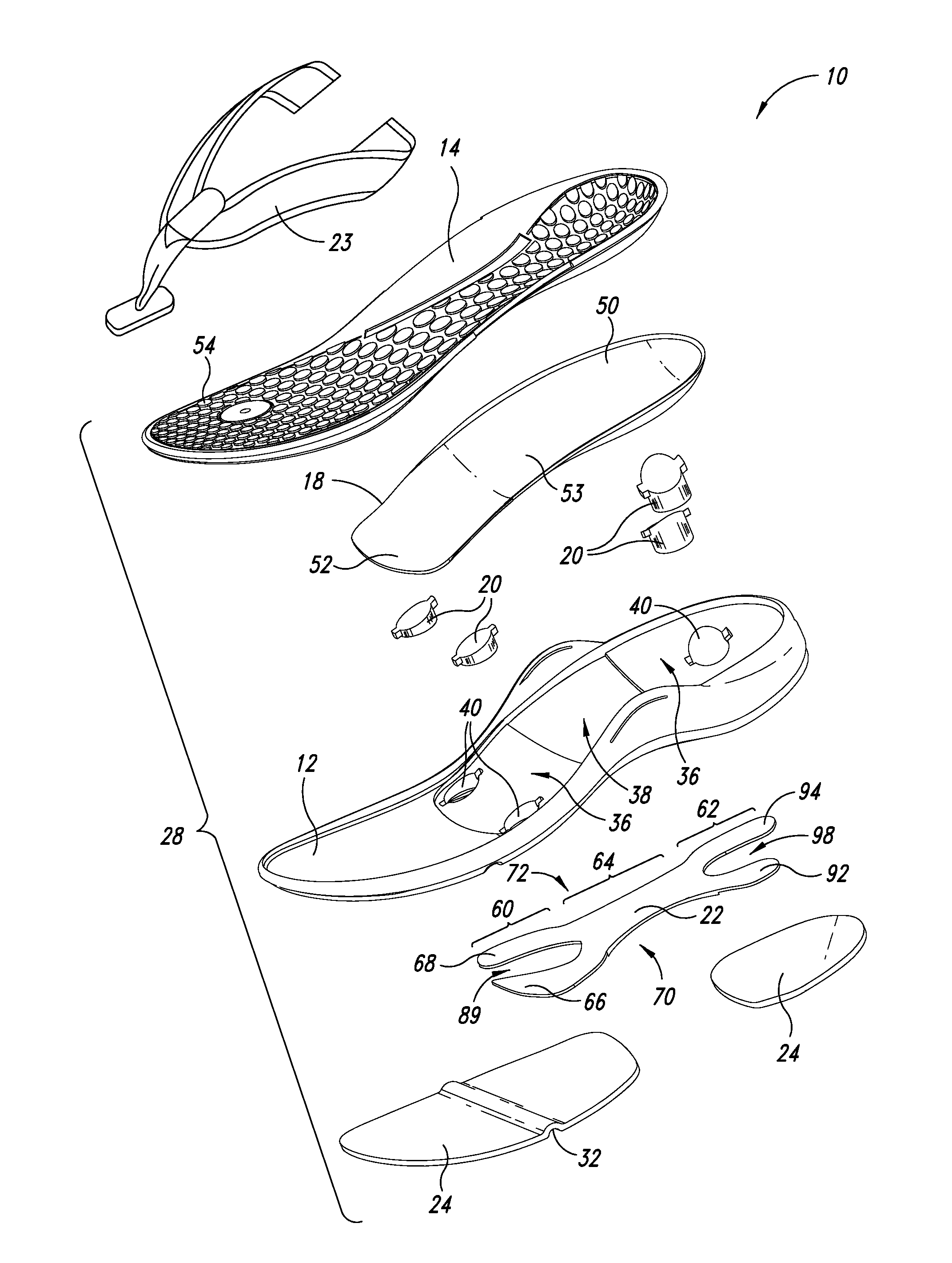
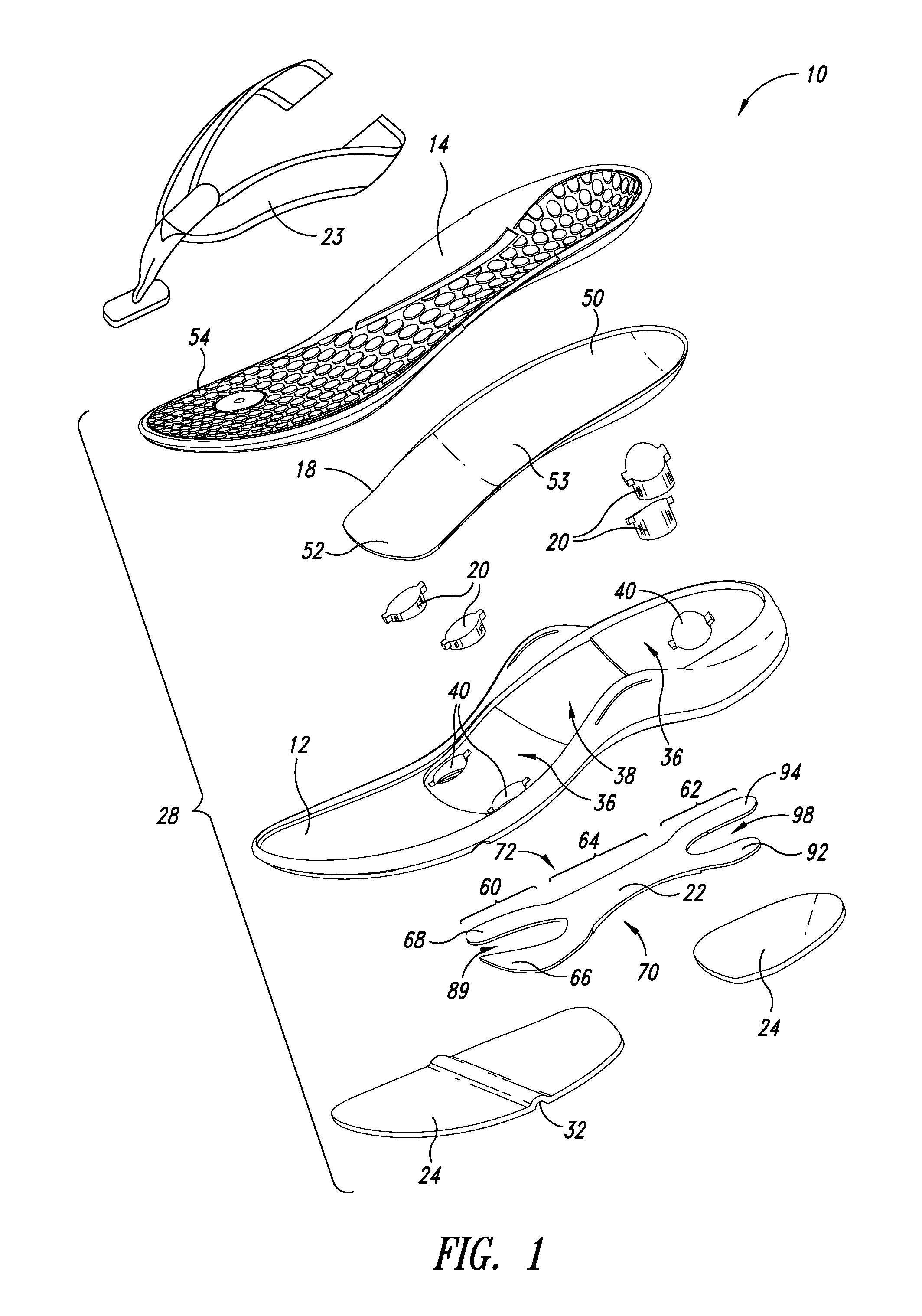
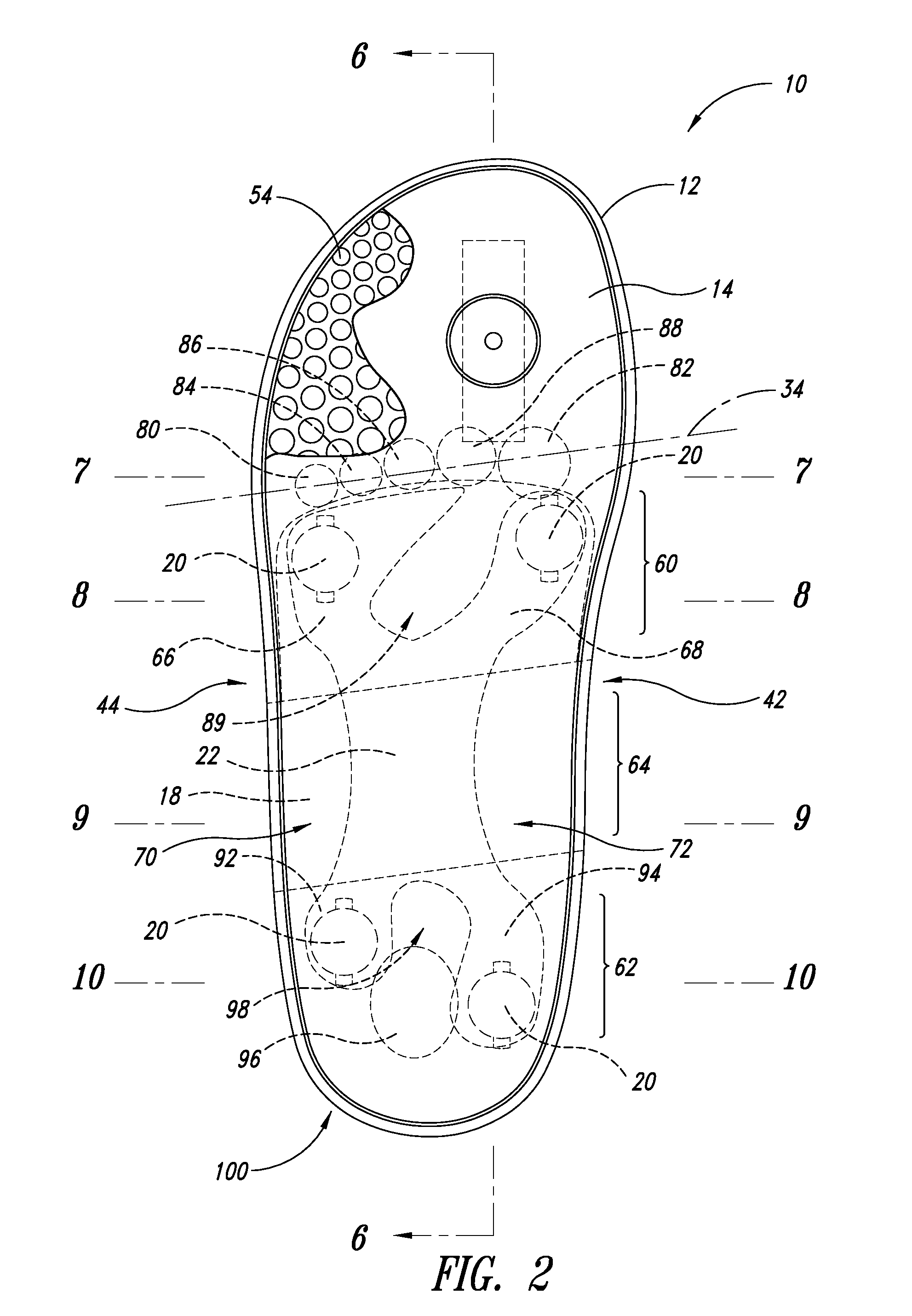
[0010]A plurality of support plugs may be positioned within the midsole platform to help to stabilize the orthotic shell in a semi-rigid position. The support plugs may extend through the midsole platform from a lower surface thereof to an opposing upper surface to come into contact with underside surfaces of the orthotic shell. The support plugs may cooperate to provide a multi-point contact structure, such as, for example, a contact structure having three, four, five or more points of contact, to hold the orthotic shell in a particularly stable manner. For instance, a pair of supports may be positioned to underlie the forefoot portion of the orthotic shell at medial and lateral sides thereof. Another pair of support plugs may be positioned to underlie the heel portion of the orthotic shell at medial and lateral sides thereof. The number of support plugs and durometer of the same may vary to provide different levels of support and comfort.
[0011]A shank is preferably coupled to the midsole platform to increase structural flexural and torsional rigidity of the footwear and provide a foundation for the support plugs. The support plugs may be positioned to span completely between portions of the shank and the orthotic shell. For example, in a four-point contact arrangement, a separate projection or arm extending from a central portion of the shank may underlie each of the support plugs which in turn contact and support the orthotic shell. More particularly, a projection of the front portion of the shank may extend along a lateral side of the footwear to underlie a region of the midsole platform behind and near a contact area corresponding to the metatarsal head of the fifth metatarsal of the foot. Another projection may extend along a medial side of the footwear to underlie a region of the midsole platform behind and near a contact area corresponding to the metatarsal head of a first metatarsal of the foot. Support plugs may be provided on these projections to semi-rigidly support the forefoot portion of the orthotic shell at medial and lateral positions. Similarly, projections may extend from the central portion of the shank toward the rear end of the footwear along lateral and medial sides of the footwear, respectively, to underlie areas transversely offset from a contact area corresponding to the posteriorly lateral aspect of the heel of the foot. Support plugs may be provided on these projections to semi-rigidly support the heel portion of the orthotic shell at medial and lateral positions. The support plugs are preferably made of a material having less pliancy than the surrounding midsole platform to reduce a compression rate of the midsole relative to a midsole formed entirely of ethylene vinyl acetate (also known as EVA) or a similar material.
[0012]Various components of the composite sole may assist in providing a wedging effect when the footwear is configured to support a wearer's forefoot in a forefoot valgus or forefoot varus position. For example, as previously discussed, the orthotic shell itself may be shaped to support the distal aspect of the metatarsal shafts proximal to the metatarsal heads in a progressively elevated position from one side of the forefoot toward an opposing side of the forefoot to simulate a forefoot valgus wedge (forefoot everted, relative to rear foot position) or a forefoot varus wedge (forefoot inverted, relative to the rear foot position). In addition, a portion of the front end of the shank may vary progressively in thickness from one side thereof to an opposing side thereof to create a wedge underlying the forefoot portion of the orthotic shell to simulate a forefoot valgus wedge (forefoot everted, relative to rear foot position) or forefoot varus wedge (forefoot inverted, relative to rear foot position). Alternatively, the midsole platform itself or an insertable support structure received therein may vary progressively in thickness from one side thereof to an opposing side thereof to create a wedge underlying the forefoot portion of the orthotic shell.
[0014]The footwear may also be formed to include several additional features to facilitate natural flexing of the foot during use. For instance, the midsole platform may include a flex groove extending across a width thereof in a position and orientation corresponding generally to a reference line defined by metatarsal phalangeal joints of the foot. In this manner, the flex groove can facilitate a natural bending of the foot at the metatarsal phalangeal joints. As another example, the shape of a front portion of the midsole platform may gradually rise to form a toe rocker feature to facilitate rolling contact of the sandal with the ground or other surface. Additionally, a rear lateral portion of the midsole platform may include an angled heel strike portion to facilitate rolling contact as the rear end of the sandal strikes the ground during use.

Problems solved by technology

On the other hand, removable inserts can be easily misplaced or lost.
In addition, orthotic inserts can become dislodged or misaligned during use, thereby diminishing their effectiveness.

Method used


Image

  • Footwear with orthotic midsole
  • Footwear with orthotic midsole
  • Footwear with orthotic midsole

Examples


Embodiment Construction

[0038]In the following description, certain specific details are set forth in order to provide a thorough understanding of various disclosed embodiments. However, one skilled in the relevant art will recognize that embodiments may be practiced without one or more of these specific details. In other instances, well-known structures and manufacturing techniques associated with footwear and orthotic devices may not be shown or described in detail to avoid unnecessarily obscuring descriptions of the embodiments.

[0039]Unless the context requires otherwise, throughout the specification and claims which follow, the word “comprise” and variations thereof, such as, “comprises” and “comprising” are to be construed in an open, inclusive sense, that is as “including, but not limited to.”

[0040]Reference throughout this specification to “one embodiment” or “an embodiment” means that a particular feature, structure or characteristic described in connection with the embodiment is included in at lea...


PUM


Abstract

Footwear is provided having a midsole platform, a full length insole and a orthotic midsole in the form of an orthotic shell received between the midsole platform and the insole. The orthotic shell has a heel portion to support a heel of a foot of a wearer and a forefoot portion to support a forefoot of the wearer at least in a region behind and near metatarsal heads of the foot. The orthotic shell is shaped to partially cup the heel and support the forefoot in one of a plurality of determined orientations. The footwear may further include a plurality of support plugs to support the orthotic shell in one of the determined orientations and a shank coupled to the midsole platform to increase torsional rigidity of the footwear with respect to a longitudinal length thereof. Methods of making footwear are also provided.

Description

CROSS-REFERENCE TO RELATED APPLICATIONS[0001]This application claims the benefit under 35 U.S.C. §119(e) of U.S. Provisional Patent Application No. 61 / 427,580 filed Dec. 28, 2010, where this provisional application is incorporated herein by reference in its entirety.BACKGROUND[0002]1. Technical Field[0003]This disclosure generally relates to footwear and orthotic devices, and more particularly to footwear and orthotic midsoles for footwear.[0004]2. Description of the Related Art[0005]Typical footwear (e.g., sandals, shoes, boots) is designed with little or no attention to providing proper support to the wearer's foot. This is particularly true for wearers who may have foot abnormalities or deformities.[0006]Such problems can be addressed using orthotic inserts (also referred to as “orthotics”), which are devices placed in footwear to cooperate with the plantar surfaces of a wearer's feet to provide various levels of support to enhance comfort and / or compensate for foot abnormalities...

Claims


Application Information

Patent Timeline
IPC IPC(8): A43B7/16A43D11/00A43B23/22
CPCA43B1/0081A43B7/141A43B7/142A43B7/144A43B7/1445A43B7/00A43B7/148A43B13/127A43B13/188A43B13/36A43B7/145A43B7/14A43B13/14A43B13/42A43B13/12
Inventor SMITH, CHRISTOPHER E.GRAY, JEFFCOLLINS, EDWARDDALEY, PETER
Owner SUPERFEET WORLDWIDE LLC
Learn More