
Computer tomographic workpiece measuring device

a workpiece and computer technology, applied in the field of computer tomographic workpiece measuring devices, can solve the problems of large mechanical dimensions, disadvantageous to the production cost, weight and installation conditions, and limited image quality and resolution, so as to reduce dimensions, increase imaging and measurement quality, and save costs

Inactive Publication Date: 2012-06-21
WENZEL VOLUMETRIK
View PDF2 Cites 37 Cited by
  • Summary
  • Abstract
  • Description
  • Claims
  • Application Information

AI Technical Summary

Benefits of technology

[0006]It is therefore the object of the present invention to improve a generic computer-tomographic workpiece measuring device with regards to its measuring and imaging properties, at the same time to create the possibility of structuring such a device more compactly and with a smaller mechanical outlay in a reliable manner.

Problems solved by technology

A conventional process of this type has the disadvantage however, that in the case of these geometric conditions and a constant instability of the x-ray tubes, undesired movements in the beam emitted by the x-ray source are present, which then show themselves on the detector side in blurring of the image.
This means that image quality and resolution are limited.
The conventional geometry of the partners involved, x-ray source, detector and support unit, also leads to devices known from the prior art typically being mechanically large, with the disadvantage associated therewith of high housing, shielding and support outlay: As a matter of principle, x-ray tomography requires (lead) shielding of the relevant passages, so that large mechanical dimensions (particularly in relation to the dimensions of a workpiece to be tested) disadvantageously affect production costs, weight and preconditions for installation (such as the requirement for additional mechanical reinforcement on a substrate).

Method used


Image

  • Computer tomographic workpiece measuring device
  • Computer tomographic workpiece measuring device
  • Computer tomographic workpiece measuring device

Examples


Embodiment Construction

)

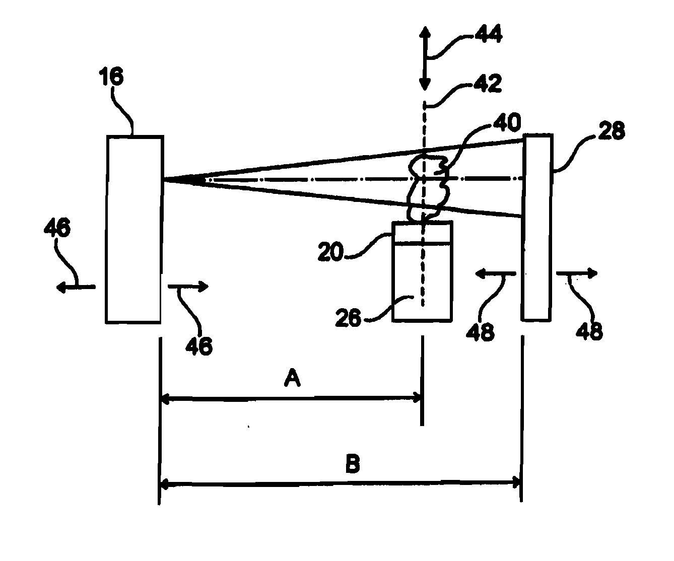
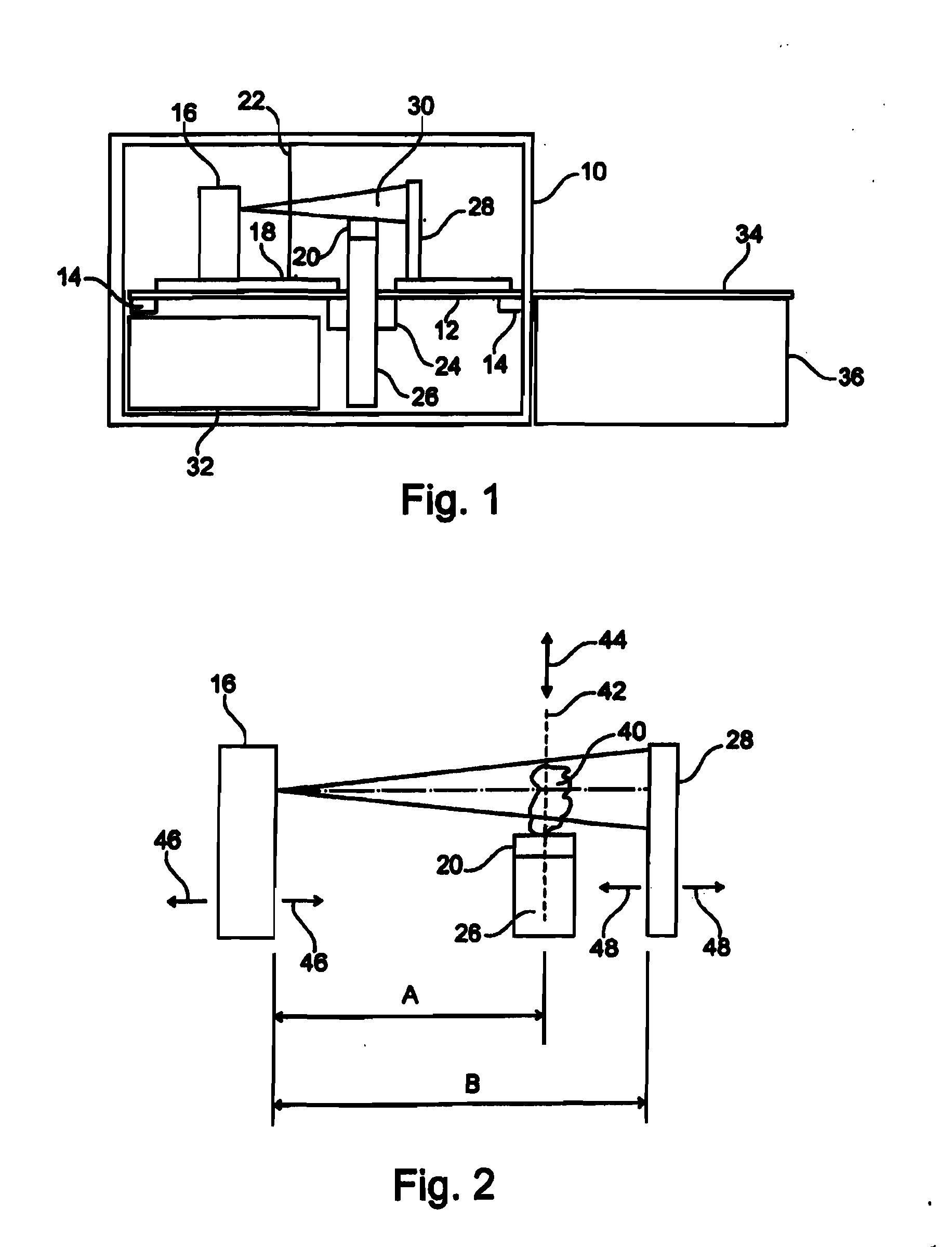
[0024]FIG. 1 clarifies in schematic side view, how, within a frame 10 offering radiation protection (e.g. by means of lead lining) on a base plate 12 (holding bed), which is supported via damper units 14 in a damping (shock and / or vibration inhibiting) manner with respect to the frame 10, an x-ray source 16 (e.g. closed microfocus or macrofocus x-ray source) is provided. The x-ray source 16 can be moved and adjusted linearly along a path, illustrated schematically by an adjustment unit 18 and also arrows 46 in FIG. 2, in order in this respect to be able to carry out an adaptation to a measurement object (workpiece) which can be provided on a rotary table 20.

[0025]Separated from the x-ray source 16 with a disc-like thermal insulation protective shield 22 which is permeable for x-ray radiation, the rotary table 20 sits on a housing unit 26 which can be moved vertically linearly by means of a bearing unit 24 and inside carries a rotary assembly (e.g. stepper motor) for driving the rot...


PUM

PropertyMeasurementUnit
Lengthaaaaaaaaaa
Sizeaaaaaaaaaa
Sizeaaaaaaaaaa

Abstract

A marine device has a floating buoy containing electronics, a submerged payload containing electrical devices and electronics, a power source and a mooring line. At least a part of the power source is submerged and electrically connected to at least one of the submerged payload and the floating buoy, and the mooring line extends between the buoy and at least one of the power source submerged part, the submerged payload and a submerged anchor having a mass allowing it to stay under the water surface.

Description

BACKGROUND[0001]The present invention relates to a computer-tomographic workpiece measuring device in accordance with the preamble of the main claim.[0002]Devices of this type for non-medical computer tomography are generally known from the prior art and are based on the measuring principle, analogous to human medical or veterinary computer tomography, of subjecting workpieces to a high-power x-ray beam as invasive radiation and radiographing the same, the workpiece typically being located as a measurement object on a rotary table as workpiece support between a (high-power) x-ray source and an electronic x-ray detector. The detector absorbs the x-ray beams penetrating the object pixel by pixel by means of suitable detector pixels. By rotating the workpiece to be measured or tested using the rotary table, a plurality of x-ray images from different directions (perspectives) can be created, which are then combined as volume data in a downstream analysis unit to form a three-dimensional...

Claims


Application Information

Patent Timeline
IPC IPC(8): H05G1/02H05G1/60
CPCG01N17/00G01N23/046G01N2223/309G01N2223/3306G01N2223/633G01N2223/3308G01N2223/408G01N2223/419G01N2223/3307B29C43/003B29C70/58B29C70/70B29K2103/04C04B35/522C04B35/532C04B35/536C04B35/634C04B35/63408C04B35/63436C04B35/6344C04B35/63444C04B35/63448C04B35/63452C04B35/63456C04B35/6346C04B35/63468C04B35/63472C04B35/63476C04B35/6348C04B2235/604F24D3/12F24D11/00F24D2220/10G01N2223/33H05B3/145G01N23/083Y02B30/00
Inventor SIMON, MARTINHEEG, SIEGFRIEDHOCK, RALFETZEL, MANFREDHILPERT, UWEEBNER, SEVERIN
Owner WENZEL VOLUMETRIK
Learn More