Digital radiographic detector array including spacers and methods for same

a radiographic detector and array technology, applied in the field of digital radiographic imaging arrays, can solve the problems of loss of resolution, image non-uniformity, and radiographic imaging arrays subjected to increased shock and/or vibration, so as to increase the fill factor of pixels, reduce crossover capacitance, and reduce the effect of crossover capacitan

Inactive Publication Date: 2012-06-21
CARESTREAM HEALTH INC
View PDF4 Cites 2 Cited by
  • Summary
  • Abstract
  • Description
  • Claims
  • Application Information

AI Technical Summary

Benefits of technology

[0013]Another aspect of the application is to provide detector imaging arrays with robust mounting of scintillating phosphor screens to imaging arrays. For example, the detector arrays can include spacers to control spacing of the scintillator from the imaging array. For example, the detector arrays can include spacers to attach the scintillator to the imaging array.
[0015]Another aspect of the application is to provide digital radiography detector imaging arrays and methods that can provide an increase in fill factor for pixels in an imaging array.
[0016]Another aspect of the application is to provide detector imaging arrays that can provide an alternative routing for metal layers (e.g., bias line), detector imaging array that can increase a fill factor of the pixel and / or maintain low or reduce crossover capacitance between at least two metal layers (e.g., bias line and other clock, data or control lines) in the pixel.
[0020]Embodiments according to present teachings can provide projection radiographic imaging apparatuses including a scintillator; an imaging array having a plurality of pixels formed over a substrate; and a plurality of spacers disposed between a surface of the imaging array and the scintillator to control spacing between the surface of the imaging layer and the scintillator. The spacers can reduce or prevent contact between a surface of the scintillator and the active surface of the imaging array.

Problems solved by technology

Greater spacing between the imaging array and the screen can result in a loss of resolution.
In addition, greater spacing or non-uniform spacing can result in image non-uniformity because of non-uniformity in optical coupling between the scintillator and the imaging array.
These digital radiography detectors subject the radiographic imaging array to increased shock and / or vibration.
In addition, for some imaging procedures, the patient stands or lies on the detector, which can result in localized regions of high pressure.
Since the imaging array 175 and scintillator 110 can be calibrated for pixel-by-pixel gain, a change in position can result in photosensitivity pattern noise because of the calibration no longer being accurate.
Since the gain calibration is obtained without pressure, localized loss of calibration accuracy can result.
For example, a planarization layer 200 can increase the distance between the scintillator 110 and the imaging array 175, which can result in additional lateral optical light piping and consequent loss in resolution.

Method used


Image

  • Digital radiographic detector array including spacers and methods for same
  • Digital radiographic detector array including spacers and methods for same
  • Digital radiographic detector array including spacers and methods for same

Examples


Embodiment Construction

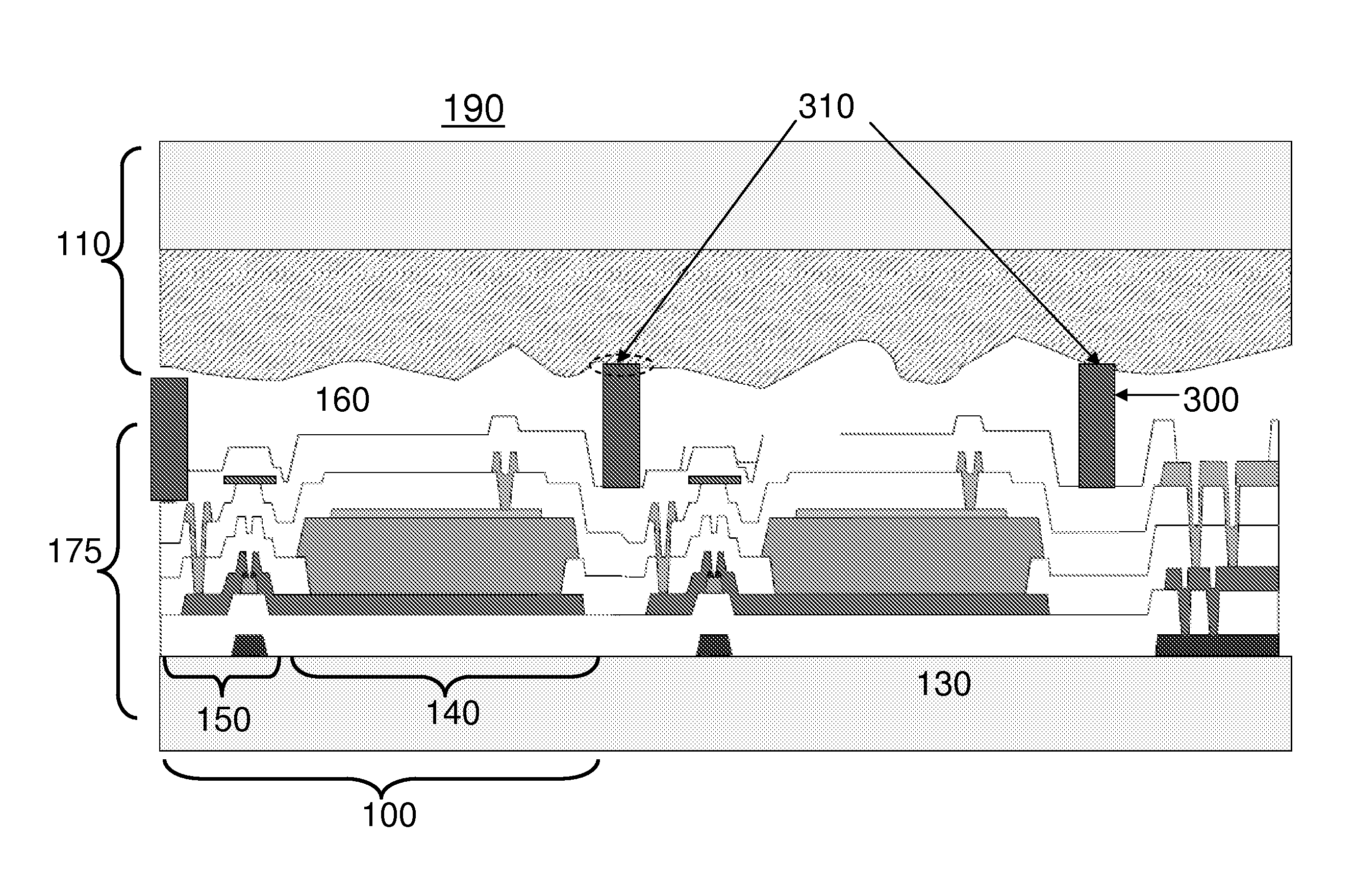
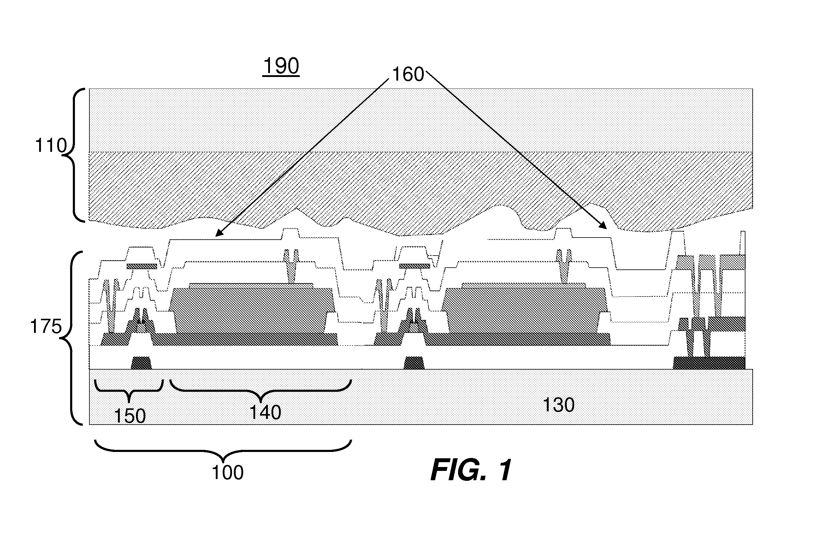
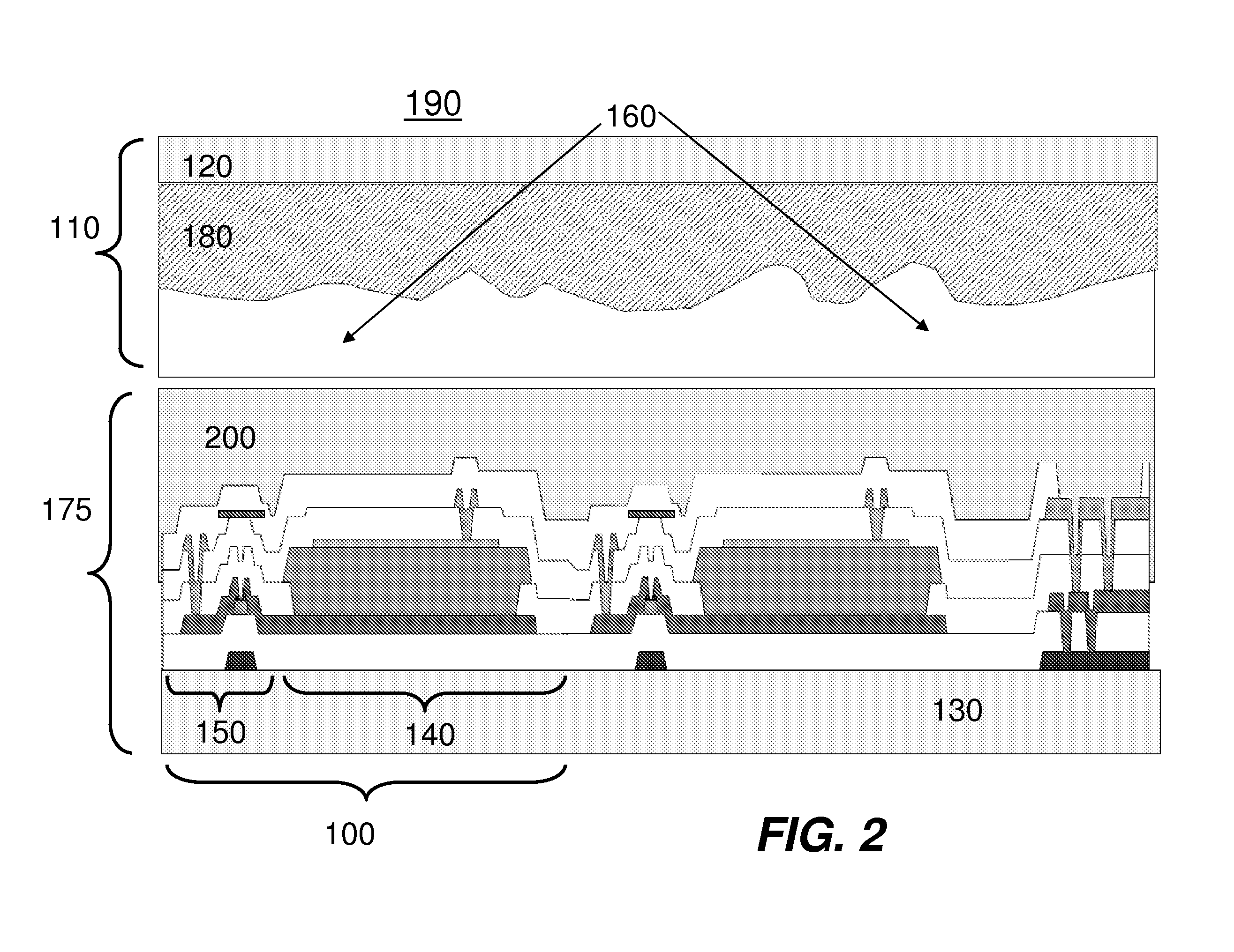
[0041]Reference will now be made in detail to the present embodiments (exemplary embodiments) of the invention, examples of which can be illustrated in the accompanying drawings. Wherever possible, the same reference numbers will be used throughout the drawings to refer to the same or like parts. In the following description, reference is made to the accompanying drawings that form a part thereof, and in which is shown by way of illustration specific exemplary embodiments in which the invention may be practiced. These embodiments are described in sufficient detail to enable those skilled in the art to practice the invention and it is to be understood that other embodiments may be utilized and that changes may be made without departing from the scope of the invention. The following description is, therefore, merely exemplary.

[0042]For simplicity and illustrative purposes, the principles of the present invention are described by referring mainly to exemplary embodiments thereof. Moreo...


PUM


Abstract

Embodiments relate to detector imaging arrays with highly robust mounting of scintillators (e.g., scintillating phosphor screens) to imaging arrays. For example, the detector arrays comprise spacers to define a space between or separate the scintillator from the imaging array. Embodiments according to present teachings can provide projection radiographic imaging apparatuses, including a scintillator, an imaging array including a plurality of pixels formed over a substrate, and a plurality of spacers disposed between an active surface of the imaging array and the scintillator. The spacers can reduce or prevent contact between a surface of the scintillator and the active surface of the imaging array, strengthen or control attachment therebetween, or adjust light transmittance therebetween.

Description

TECHNICAL FIELD[0001]The present application relates to digital radiographic imaging arrays. More specifically, the present application relates to indirect digital radiographic imaging arrays and methods for using the same.DESCRIPTION OF RELATED ART[0002]An indirect digital radiographic (DR) detector can include a scintillator (e.g., phosphor scintillating screen) arranged in proximity to an imaging array sensitive to radiation emitted by the scintillator upon absorption of X-rays. In order to maintain high resolution, the scintillating screen can be mounted in contact with the imaging array or within about 1 micron of a surface of the imaging array. Greater spacing between the imaging array and the screen can result in a loss of resolution. For example, this loss of resolution can occur because of multiple reflections of light between the scintillator and the active surface of the imaging array (this phenomena is called light-piping). In addition, greater spacing or non-uniform spa...

Claims


Application Information

Patent Timeline
Patent Type & Authority Applications(United States)
IPC IPC(8): G01T1/20H01L31/18
CPCH01L27/14663H01L27/14603
Inventor TREDWELL, TIMOTHY J.
Owner CARESTREAM HEALTH INC
Why Eureka
Try Eureka