
Assembly and noise suppressor for firearms

Inactive Publication Date: 2012-06-21
KOUMBIS GEORGE
View PDF12 Cites 44 Cited by
  • Summary
  • Abstract
  • Description
  • Claims
  • Application Information

AI Technical Summary

Benefits of technology

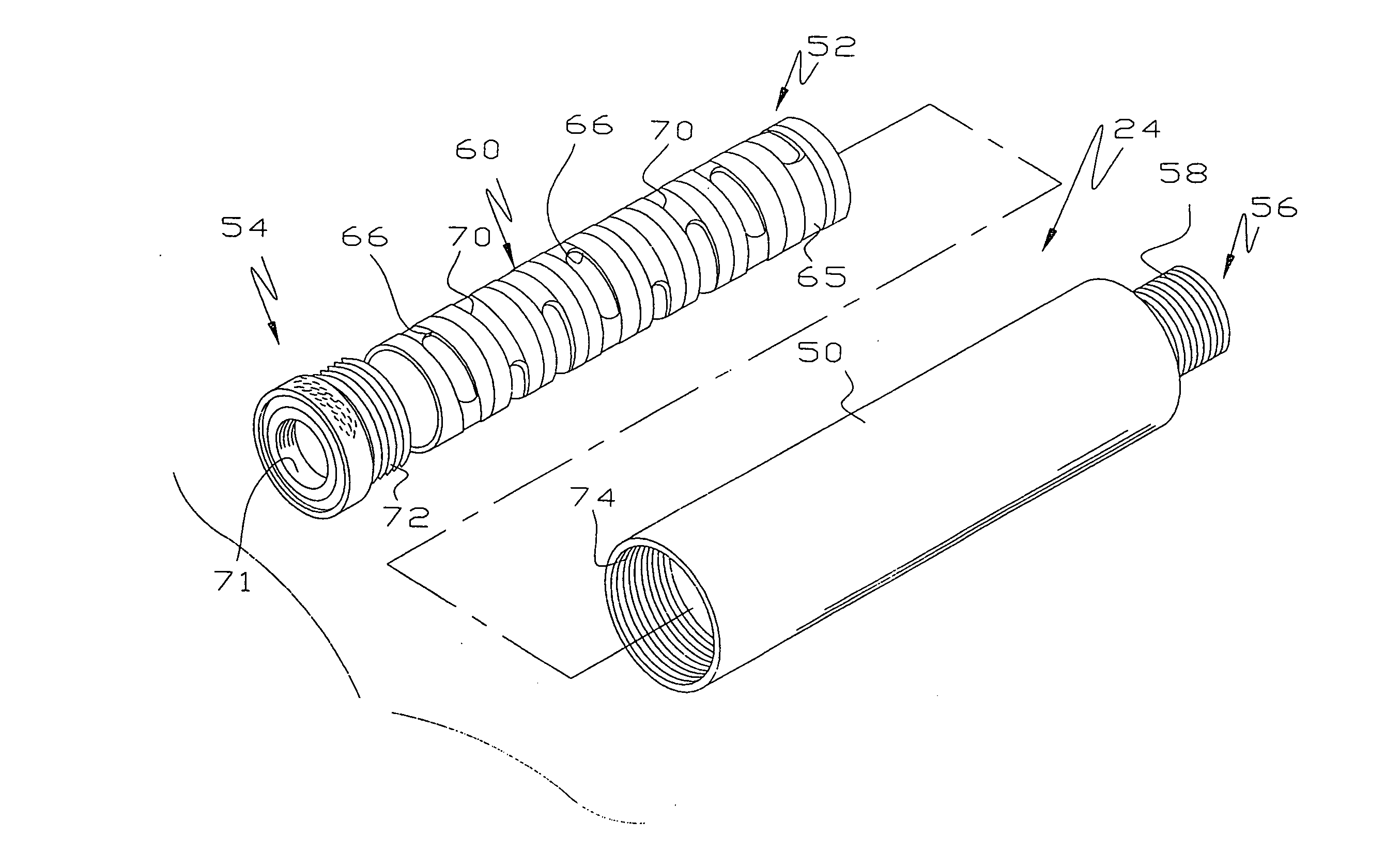
[0005]In this invention, an assembly is attached to the receiver of the rifle or to the barrel adjacent the junction of the barrel and receiver so the assembly is supported independently of the end of the barrel from which the projectile emerges. This is accomplished by securing a rigid load bearing support, which acts as a heat shield or stabilizer tube, to the receiver or to the barrel adjacent its junction with the receiver and attaching a noise suppressor to the support. Thus, the weight of the noise suppressor is not supported on the discharge end of the barrel so the accuracy of the firearm is not adversely affected by the weight of the suppressor. The support comprises an imperforate sleeve connected to the receiver or to the receiver end of the barrel. In most embodiments, the sleeve is threaded onto the receiver. The sleeve extends somewhat past the discharge end of the barrel. A noise suppressor is fixed to the distal end of the sleeve and provides a passage aligned with the barrel passage so fired projectiles pass seamlessly through the noise suppressor. The noise suppressor is preferably threaded onto the sleeve end.
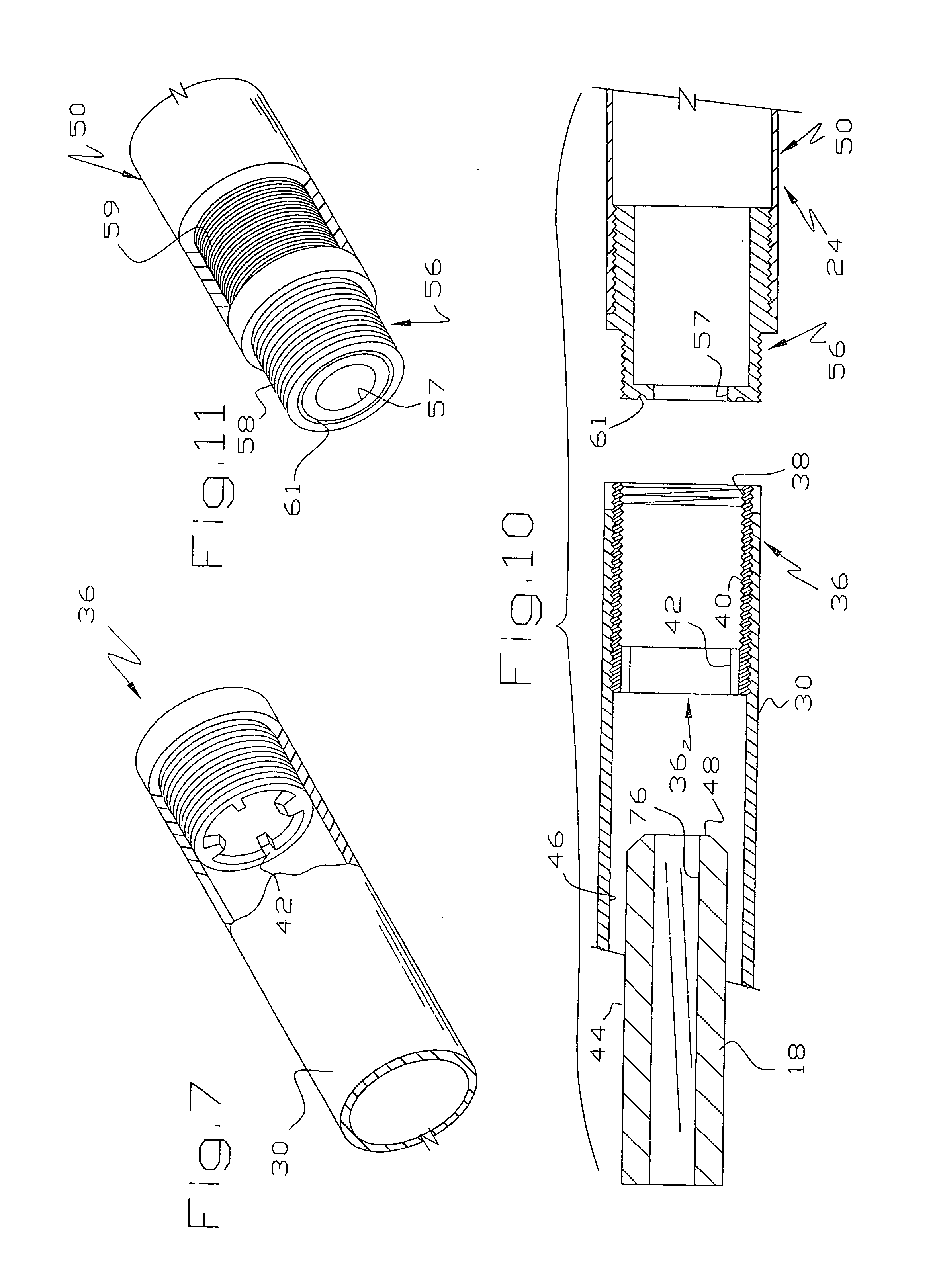
[0006]This approach has many advantages. First, the weight of the noise suppressor is transmitted by the sleeve to the receiver independently of the barrel so the weight of the noise suppressor does not distort the barrel nor affect the point of impact of projectiles. Second, the annulus between the barrel exterior and the sleeve interior provides an expansion chamber for cooling propellant gases thereby enhancing the silencing ability of the device. Third, because the sleeve and noise suppressor are readily removable from the receiver, the device is easy to clean without sophisticated cleaning equipment. Fourth, projections on the inside of the sleeve abut the barrel near its discharge end damp barrel harmonic vibrations thereby promoting smaller impact groups.

Problems solved by technology

Third, because the sleeve and noise suppressor are readily removable from the receiver, the device is easy to clean without sophisticated cleaning equipment.
Fourth, projections on the inside of the sleeve abut the barrel near its discharge end damp barrel harmonic vibrations thereby promoting smaller impact groups.

Method used


Image

  • Assembly and noise suppressor for firearms
  • Assembly and noise suppressor for firearms
  • Assembly and noise suppressor for firearms

Examples


Embodiment Construction

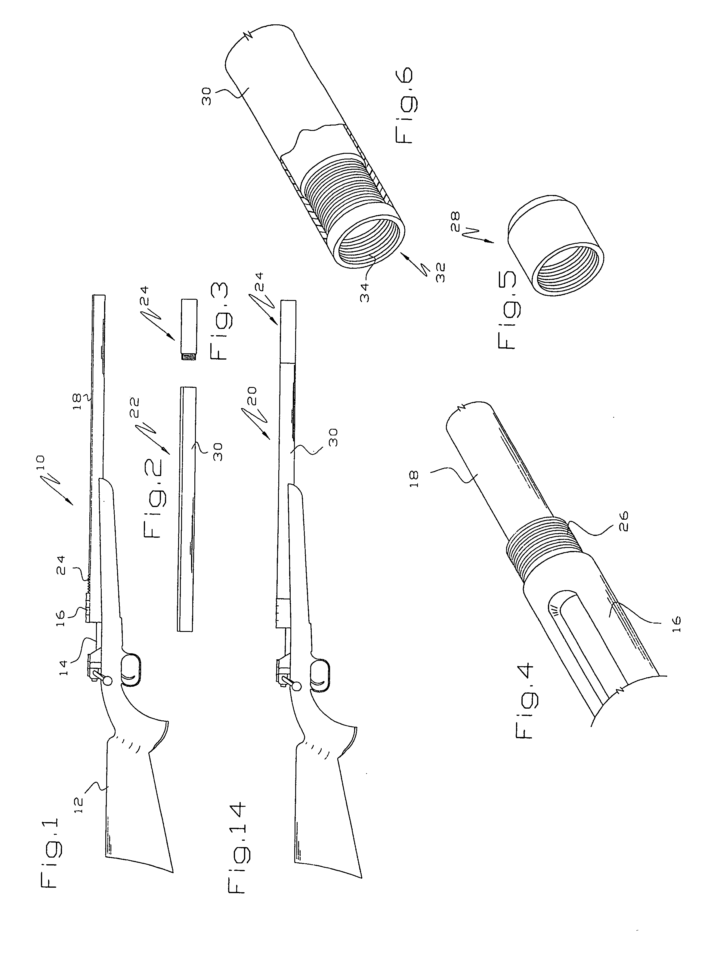
[0027]Referring to FIGS. 1-11, a rifle 10 is illustrated as of a bolt action type having a stock 12, a bolt 14, a receiver 16 and a barrel 18. Those skilled in the art will recognize the rifle 10 as being a conventional rifle known as a Fabrique National (FN) of the free floating barrel type where the barrel is attached to the receiver 16 but is slightly movable relative to the stock 12. Those skilled in the art will recognize that free floating barrel type rifles comprise the majority of modern “counter sniper” weapons, as well as for all versions of the M16 and its civilian version, the AR15.

[0028]As shown by a comparison of FIGS. 1 and 14, the rifle 10 has been modified by incorporating an assembly 20 which includes a rigid imperforate sleeve or tubular beam22 and a noise suppressor 24. The sleeve 22 is fixed to the receiver 16 or to the barrel 18 adjacent its junction with the receiver 16 in any suitable manner, as by welding, mating threads, adhesives or the like. Preferably, t...


PUM


Abstract

An assembly for a firearm (10) includes a sleeve (22) connected to the receiver or receiver end of the barrel (18). The sleeve (22) extends beyond the discharge end of the barrel (18) and includes inwardly extending projections (42) abutting or juxtaposed to a peripheral section (44) of the discharge end of the barrel (18). A noise suppressor (24, 50) threads onto the sleeve (22). Some of the propellant gases are redirected and cooled by the noise suppressor (24, 50) in a conventional manner. Some of the propellant gases are redirected into an annulus (46) between the barrel (18) and sleeve (22) where they are cooled and some of their volume is reduced thereby increasing the efficiency of the noise suppressor (24, 50).

Description

[0001]This application is based on Provisional Patent Application Ser. No. 61 / 066,705, filed Feb. 21, 2008 on which priority is claimed and PCT / US2009 / 001062 filed Feb. 19, 2009.[0002]This invention relates to an assembly and noise suppressor for rifles, automatic weapons, pistols, shotguns and similar firearms.BACKGROUND OF THE INVENTION[0003]Conventional silencers or noise suppressors are devices attached to the barrel of rifles, pistols and similar firearms for reducing the noise attendant upon firing of ammunition. Silencers are typically attached by machining threads on the discharge end of the barrel and then threading the silencer onto the barrel. This has a number of disadvantages, most particularly in high accuracy rifles, because the weight of the silencer deflects the barrel enough to affect the point of impact of rounds fired through the barrel. Given the strength of rifle barrels, this may sound implausible but is an awkward fact. Sniper rifles are equipped with scopes ...

Claims


Application Information

Patent Timeline
IPC IPC(8): F41A21/30
CPCF41A21/30
Inventor KOUMBIS, GEORGE
Owner KOUMBIS GEORGE
Learn More