
Rotary switch valve and shower group with rotary switch valve

a technology of rotary switch valve and shower group, which is applied in the direction of multiple way valve, transportation and packaging, mechanical equipment, etc., can solve the problems of high cost, complicated procedure, and cockamamie effect, and achieve the effect of small hand effort and convenient operation

Inactive Publication Date: 2012-06-14
XIAMEN SOLEX HIGH TECH IND CO LTD
View PDF3 Cites 11 Cited by
  • Summary
  • Abstract
  • Description
  • Claims
  • Application Information

AI Technical Summary

Benefits of technology

[0003]The object of the present invention is to offer a rotary switch valve, it is convenient to choose different water outlets in the shower equipment and its structure is simple.
[0004]Another object of the present invention is to offer a shower group with rotary switch valve, which overcomes the structure complexity and inconvenient to use of the shower equipment in the background of the present invention.
[0026]Compared with the technology in the background, the beneficial of the present invention are: 1 the first water outlet, the second water outlet and a water inlet are directly set on the main body of the rotary switch valve disclosed in the present invention, said water outlets are connected to different let-off pipe, the on and off of the first water outlet and / or the second water outlet are controlled by rotating the let-off pipe without installing control wrench, so that the structure is simply; 2 the let-off pipe and the rain shower are connected and supported by the arm tube without hose in the shower equipment of the present invention, the switch of the pipe and the rain shower are easily achieved by swinging the let-off pipe, so that the switch of the fixed shower and the hand-held shower is conveniently achieved, the users can directly hold and swing the arm tube, the actuating arm is long, and the hand effort is small and convenient, there is no need to stand on a foot pad or other high structure for the users; 3 all of the shower equipment's components are tightly fixed, well sealed and the structure is compact; 4 the fixed axle can work as fixed joint, hinge axle and locating the rotation of the axle simultaneously.

Problems solved by technology

For combining the function of the fixed shower and the hand-held shower at the prior art, the water outlet is connected to one end of the hose, the other end of the hose is connected to the shower, and a converter is needed, it is complicated and high-cost and turns the procedure to be cockamamie.

Method used


Image

  • Rotary switch valve and shower group with rotary switch valve
  • Rotary switch valve and shower group with rotary switch valve
  • Rotary switch valve and shower group with rotary switch valve

Examples


embodiment 1

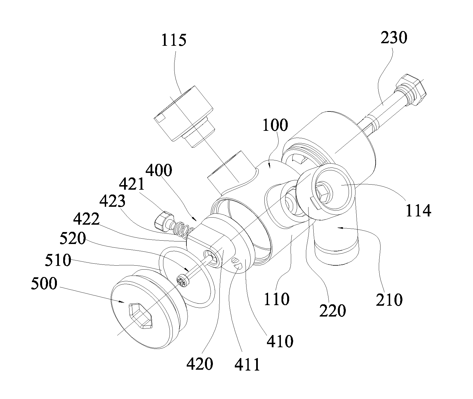
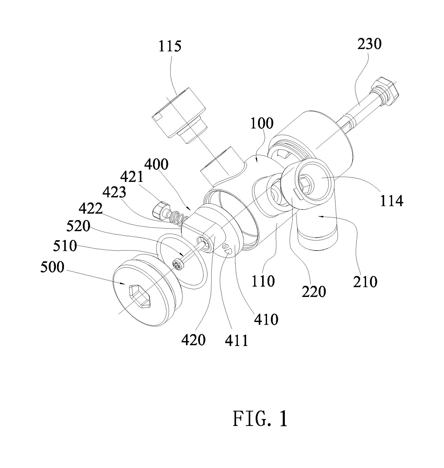
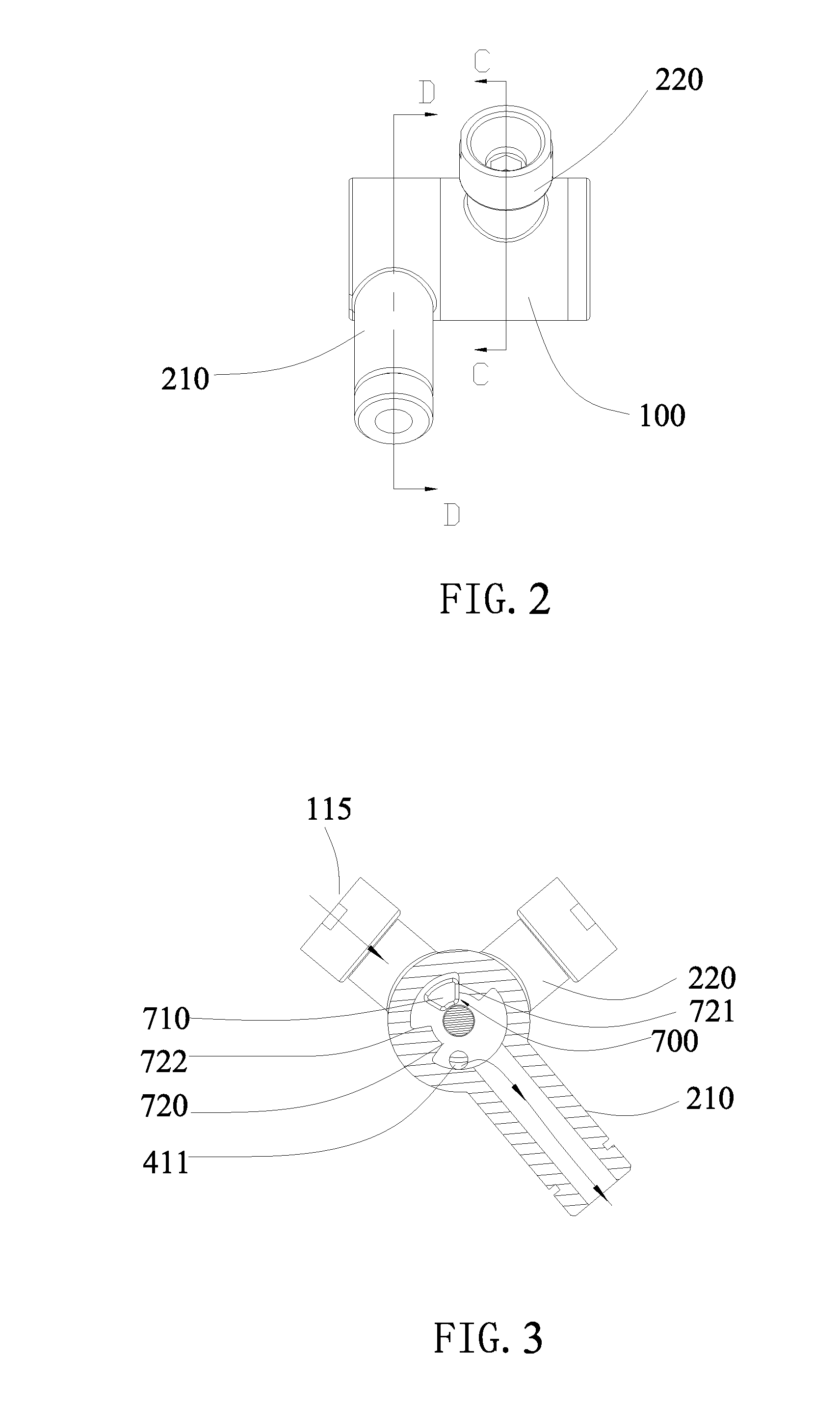
[0045, according to FIGS. 1, 2, 3, 4, 5, 6 and 7, the rotary switch valve 1 in the present invention comprises:

[0046]A main body 100, it comprises a sleeve body 110 and a division board 120 hermetically set in the sleeve body 110, the division board 120 divides the sleeve body 110 into a front cavity 111 and a back cavity 112; the division board 120 has the first water outlet 113 that connects the front cavity 111 with the back cavity 112, the sleeve body 110 has a water inlet 115 that connects the front cavity 111 and the second water outlet 114 that connects the front cavity 111; the center of the division board 120 has a hinge hole whose axis coincides with the axis of the sleeve body.

[0047]The first let-off pipe are L-shape pipeline 210 that is rotationally connected to the back cavity 112 after the sleeve body 110, the L-shape pipeline 210 has an entry end 211 and an effluent end 212, said entry end 211 is hinged and joined after the sleeve body 110 and connects the back cavity...

embodiment 2

[0055, according to FIGS. 1, 2, 3, 4, 5, 6, 7, 8 and 9,

[0056]A shower group with rotary switch valve comprises the rotary switch valve 1, the head shower 2, the rain shower 3 and the arm tube 4.

[0057]The structure of the rotary switch valve 1 is the same to the embodiment 1, and it is not mentioned here.

[0058]A head shower 2, which is connected to the effluent end of the rotary switch valve's first let-off pipe (L-shape pipeline), is connected to the first water outlet 113. In this embodiment, a universally regulate structure is set between the head shower 220 and the effluent end, and can be slightly adjusted universally;

[0059]A rain shower 3, which is fixed to the second let-off pipe 220 of the rotary switch valve 1 and connected to the second water outlet 114;

[0060]A arm tube 4, it is fixed to the end of the water inlet 115 of the rotary switch valve 1.

[0061]FIGS. 2, 3, 4 and 9 show the abridged general view according to the preferred embodiment of the shower group with rotary sw...

embodiment 3

[0064 is according to the FIGS. 10 and 11.

[0065]The difference between the embodiment 3 and the previous embodiments are: there is a multi-heads shower 5 is connected to the first let-off pipe (L-shape pipeline 210) of the rotary switch valve 1 in the present invention. The effluent of the multi-heads shower 5 and / or the rain shower 3 can be controlled by rotating the rod piece of the multi-heads shower 5.


PUM


Abstract

A rotary switch valve has a main body with a division board hermetically set in a sleeve body and the sleeve body and has a water inlet and two water outlets, a let-off pipe rotationally joined to the back of the sleeve body and connected to the back cavity, and a water division plate which is rotationally set in the sleeve body to rotate between the first and second position and is fixed to the let-off pipe to rotate along the let-off pipe to connect or cut off the water outlet in the first water outlet or the second water outlet. The shower group with the rotary switch valve has an arm tube, a rain shower connected to the first water outlet and a head shower connected to the second water outlet. The head shower water outlets and the rain shower can be switched by rotating the let-off pipe.

Description

FIELD OF THE INVENTION[0001]The present invention relates to a shower equipment, more particularly to a rotary switch valve and a shower group with rotary switch valve.BACKGROUND OF THE INVENTION[0002]For combining the function of the fixed shower and the hand-held shower at the prior art, the water outlet is connected to one end of the hose, the other end of the hose is connected to the shower, and a converter is needed, it is complicated and high-cost and turns the procedure to be cockamamie. The invention “a shower water outlet converter” (CN810007479.6) discloses a shower water outlet converter, it comprises a water inlet, two water outlet and a conversion wrench cover, a hose is connected to the first water outlet, the other end of the hose is connected to the hand-held shower, the second water outlet is connected to the fixed shower, a special wrench control converter is needed to control and switch different water outlets.SUMMARY OF THE INVENTION[0003]The object of the presen...

Claims


Application Information

Patent Timeline
Patent Type & Authority Applications(United States)
IPC IPC(8): B05B15/00F16K11/02
CPCB05B1/18B05B1/1645Y10T137/86863Y10T137/87249A47K3/28
Inventor ZHOU, HUASONGCHEN, TIANYULIU, ZIGUANGLI, QINGSHUANG
Owner XIAMEN SOLEX HIGH TECH IND CO LTD
Learn More