
Method for Implementing Timing Point Engineering Change Orders in an Integrated Circuit Design Flow

a technology of engineering change orders and integrated circuits, applied in computer aided design, program control, instruments, etc., can solve problems such as reversing some fixes, complex design cycle of integrated circuits, and unintended consequences of other related timing paths, so as to achieve faster switching speed, faster switching speed, and slower switching speed

Inactive Publication Date: 2012-06-07
APPLE INC
View PDF25 Cites 9 Cited by
  • Summary
  • Abstract
  • Description
  • Claims
  • Application Information

AI Technical Summary

Benefits of technology

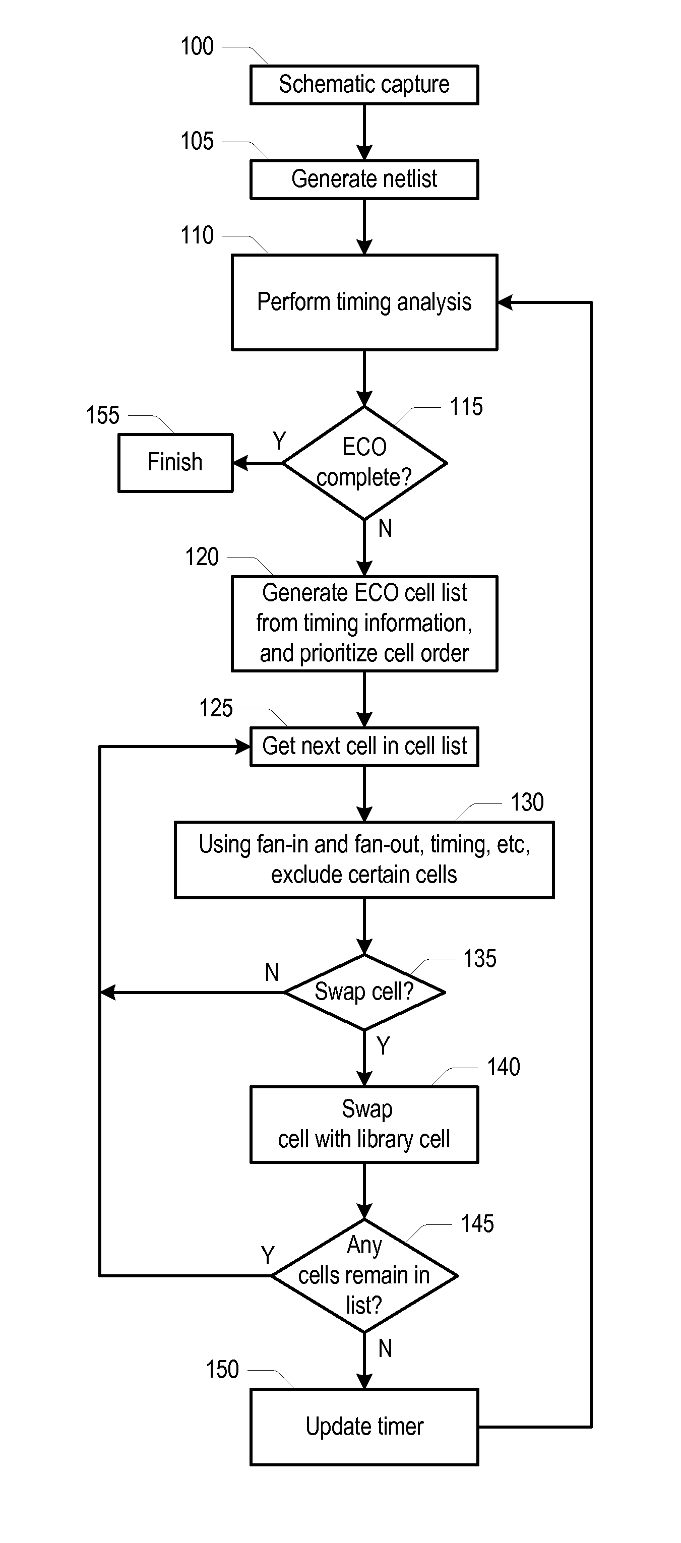
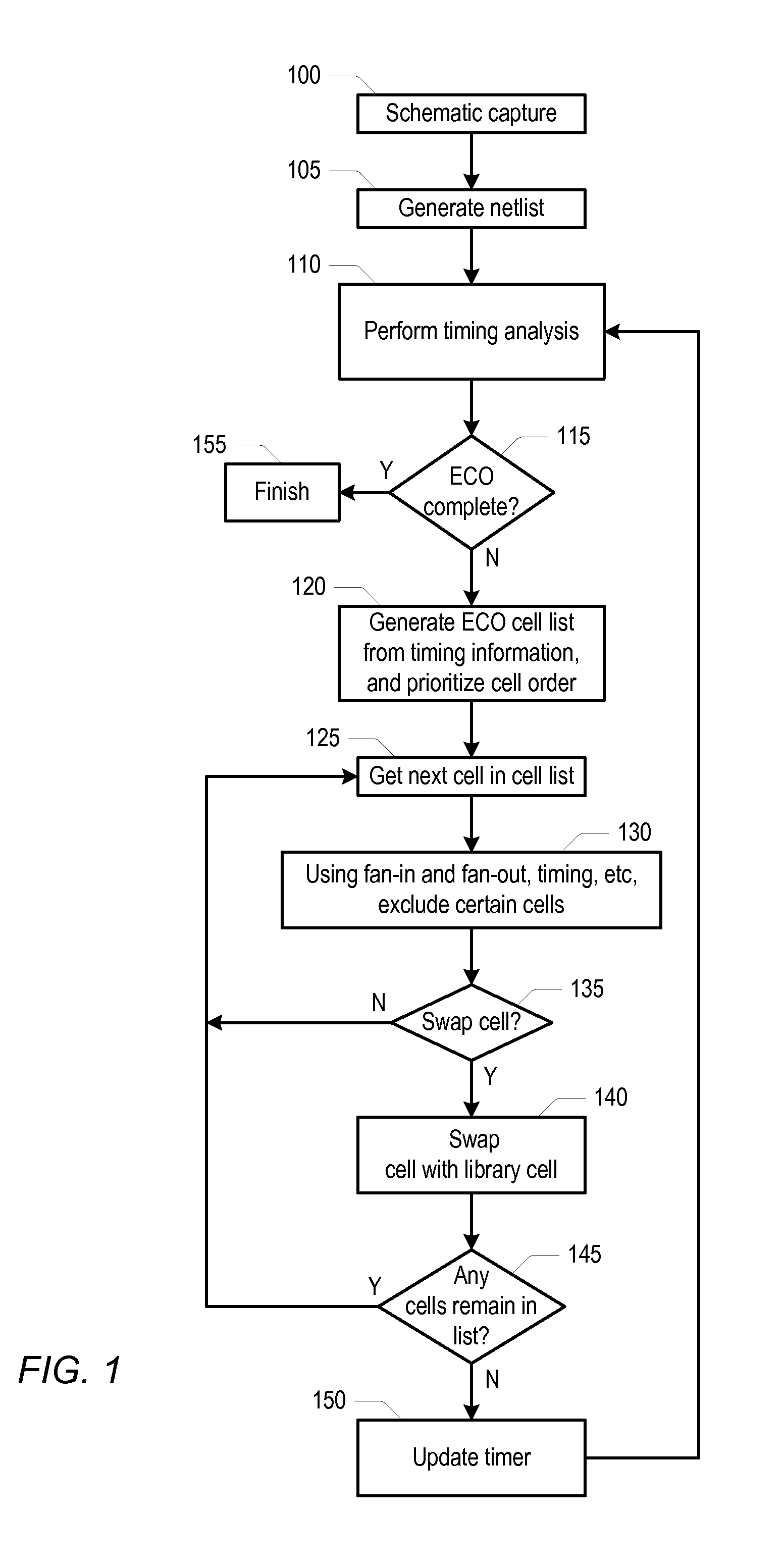
The patent describes a method and system for automatically correcting engineering change orders (ECOs) in an integrated circuit (IC). The method involves analyzing the timing of a netlist of the IC and annotating each device cell with a worst timing slack. The system then generates an ECO list of cells that need correction and prioritizes the correction order based on cell attributes such as size and speed. The method also excludes certain cells based on their fan-in or fan-out connection paths and replaces them with different cells from a design library. The system also performs power analysis to identify devices with high power consumption and replaces them with devices that have faster or slower switching speeds. The technical effects of this patent include improved efficiency and accuracy in identifying and correcting ECOs, reducing power consumption, and improving overall performance of the IC.

Problems solved by technology

The design cycle for integrated circuits is complex and there are many steps.
However, in many cases swapping a gate in a timing path of interest may cause unintended consequences in other related timing paths.
These conventional ECO tools may repair several timing paths and then have to go back and undo some of the fixes because of the unintended timing problems created in the other paths.
This can lead to unacceptably long delays in getting convergence in timing path errors, and thus delays in closure of the design cycle.

Method used


Image

  • Method for Implementing Timing Point Engineering Change Orders in an Integrated Circuit Design Flow
  • Method for Implementing Timing Point Engineering Change Orders in an Integrated Circuit Design Flow
  • Method for Implementing Timing Point Engineering Change Orders in an Integrated Circuit Design Flow

Examples


Embodiment Construction

[0007]Various embodiments of a method and system for automatically implementing engineering change order (ECO) corrections in an integrated circuit (IC) are disclosed. In one embodiment, the method includes a design tool performing a timing analysis for a netlist of the IC that includes a listing of device cells. The method may also include annotating each of the device cells in the listing with a worst timing slack through a respective timing point associated with the device cell. In addition, the method may include generating an ECO list of device cells needing ECO correction and prioritizing the ECO correction order of the device cells in the ECO list based upon cell attributes such as cell size and / or speed for example. The method may further include excluding one or more device cells in the ECO list based upon the fan-in or fan-out connection path of other device cells in the ECO list that will be corrected, and the design tool selecting device cells in the ECO list and replaci...


PUM


Abstract

A method and system for automatically implementing engineering change order (ECO) corrections in an integrated circuit (IC) include a design tool performing a timing analysis on a netlist of the IC. The method may also include annotating each of the device cells with a worst timing slack through a respective timing point associated with the device cell. In addition, the method may include generating an ECO list of device cells needing ECO correction and prioritizing the ECO correction order of the device cells in the ECO list based upon cell attributes. The method may further include excluding device cells in the ECO list based upon the fan-in or fan-out connection path of other device cells in the ECO list that will be corrected, and the design tool selecting and replacing device cells in the ECO list with different device cells from a design library.

Description

[0001]This patent application claims priority to Provisional Patent Application Ser. No. 61 / 420,173, filed Dec. 6, 2010, the content of which is herein incorporated by reference in its entirety.BACKGROUND[0002]1. Technical Field[0003]This disclosure relates to integrated circuit design, and more particularly to a method for correcting timing path violations.[0004]2. Description of the Related Art[0005]The design cycle for integrated circuits is complex and there are many steps. During the design cycle there are many timing checks performed to ensure that signal paths meet specified timing. Generally, once the circuit has been synthesized, placed, and routed, changes to the circuit are referred to as engineering change orders or ECOs.[0006]In a typical conventional ECO design flow the static timing path analyzer (STA) may provide a list of timing paths that do not meet timing. The conventional ECO tools may make changes to the problem timing paths in various ways. For example, one or...

Claims


Application Information

Patent Timeline
Patent Type & Authority Applications(United States)
IPC IPC(8): G06F17/50
CPCG06F2217/84G06F17/5031G06F30/3312G06F2119/12
Inventor KAMDAR, CHETAN C.XIA, LIANG
Owner APPLE INC
Learn More