Method and apparatus for transmitting reference signal
a reference signal and signal technology, applied in the field of mobile communication, can solve the problems become and the problem of how to send demodulation reference signals (dm rs) is a problem to be solved
- Summary
- Abstract
- Description
- Claims
- Application Information
AI Technical Summary
Benefits of technology
Problems solved by technology
Method used
Image
Examples
first embodiment
The First Embodiment
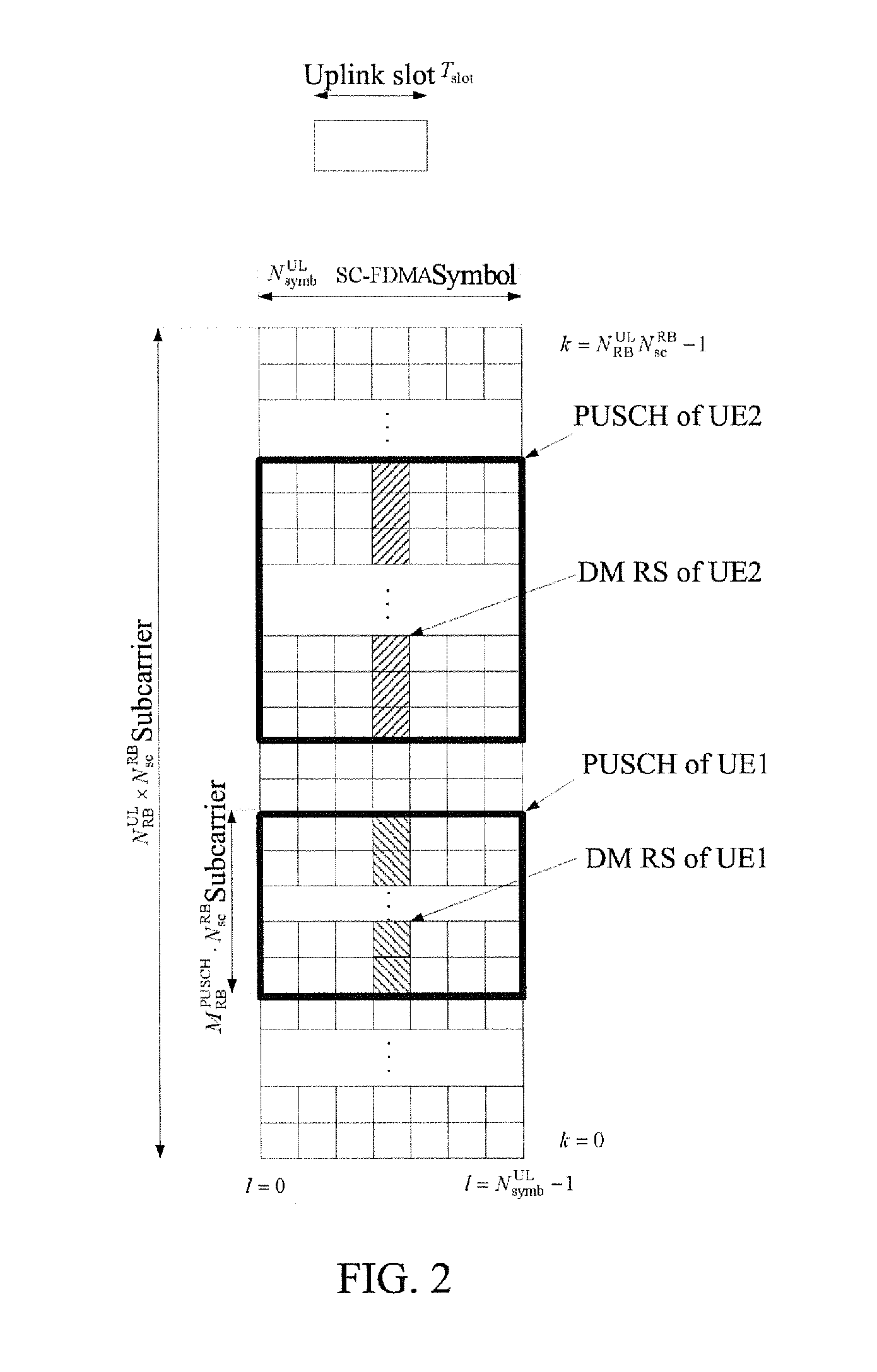
[0119]As shown in FIG. 6, assuming that in the LTE-A system, the PUSCH of a user equipment 1 is transmitted on a component carrier, and the uplink system bandwidth of this component carrier is 20 MHz, corresponds to 12 PRBs and 144 subcarriers in frequency domain, and is divided into two sections of non-continuous bandwidth in frequency domain using non-continuous resource allocation, the two sections of bandwidth corresponding to 4 PRBs and 48 subcarriers and 8 PRBs and 96 subcarriers respectively.
[0120]The user equipment 1 transmits demodulation reference signals (DM RS) for the PUSCH on the two sections of bandwidth occupied by the PUSCH of the user equipment 1.
[0121]The DM RSs on each section of bandwidth are an independent sequence.
[0122]The DM RS sequence rPUSCH,0(•) on the 0th section of bandwidth is defined as
rPUSCH,0(m·MscRS+n)=ru,v0(α)(n)
where
m=0,1
n=0, . . . , MscRS−1
[0123]The sequence length is the number of subcarriers corresponding to the section of ...
second embodiment
The Second Embodiment
[0133]As shown in FIG. 7, assuming that in the LTE-A system, the PUSCH of a user equipment 1 is transmitted on a component carrier, and the uplink system bandwidth of this component carrier is 20 MHz, corresponds to 12 PRBs and 144 subcarriers in frequency domain, and is divided into two sections of non-continuous bandwidth in frequency domain using non-continuous resource allocation, the two sections of bandwidth corresponding to 4 PRBs and 48 subcarriers and 8 PRBs and 96 subcarriers respectively.
[0134]The UE1 transmits demodulation reference signals (DM RS) for the PUSCH on the two sections of bandwidth occupied by the PUSCH of the UE1.
[0135]The DM RSs on each section of bandwidth are a part of an independent sequence rPUSCH(•), and rPUSCH(•) is defined as
rPUSCH(m·MscRS+n)=ru,v(α)(n)
where
m=0,1
n=0, . . . , MscRS−1
and
MscRS=144
[0136]m=0,1 correspond to two slots in a subframe (1 ms) respectively.
[0137]The DM RS sequence rPUSCH,0(•) on the 0th section of bandwidt...
third embodiment
The Third Embodiment
[0144]As shown in FIG. 8, assuming that in the LTE-A system, the PUSCH of a user equipment 1 is transmitted on a component carrier, and the uplink system bandwidth of this component carrier is 10 MHz, corresponds to 24 PRBs and 288 subcarriers in frequency domain, and is divided into three sections of non-continuous bandwidth in frequency domain using non-continuous resource allocation, the three sections of bandwidth corresponding to 6 PRBs and 72 subcarriers, 12 PRBs and 144 subcarriers and 6 PRBs and 72 subcarriers respectively.
[0145]The UE1 transmits demodulation reference signals (DM RS) for the PUSCH on the three sections of bandwidth occupied by the PUSCH of the UE1.
[0146]The DM RSs on each section of bandwidth are an independent sequence.
[0147]The DM RS sequence rPUSCH,0(•) on the 0th section of bandwidth is defined as
rPUSCH,0(m·MscRS+n)=ru,v0(α)(n)
where
m=0,1
n=0, . . . , MscRS−1
[0148]the sequence length is the number of subcarriers corresponding to the se...
PUM
 Abstract
Description
Claims
Application Information
 - R&D
- Intellectual Property
- Life Sciences
- Materials
- Tech Scout
- Unparalleled Data Quality
- Higher Quality Content
- 60% Fewer Hallucinations
Browse by: Latest US Patents, China's latest patents, Technical Efficacy Thesaurus, Application Domain, Technology Topic, Popular Technical Reports.
© 2025 PatSnap. All rights reserved.Legal|Privacy policy|Modern Slavery Act Transparency Statement|Sitemap|About US| Contact US: help@patsnap.com


