
Reflection type display device

a display device and display technology, applied in the field of reflection type display devices, can solve the problems of low light utilization efficiency, display device disclosed in patent literature 1 has a risk of deterioration of display performance, and conventional techniques, and achieve the effect of high light utilization efficiency

Inactive Publication Date: 2012-06-07
SHARP KK
View PDF5 Cites 8 Cited by
  • Summary
  • Abstract
  • Description
  • Claims
  • Application Information

AI Technical Summary

Benefits of technology

[0027]In view of this, the present invention was made to solve the problems. An object of the present invention is to provide a reflection type display device which achieves a high light utilization efficiency and high-definition display.
[0031]According to the arrangement, after passing through the metal nanoparticles, the light having a specific wavelength is reflected by the reflector, and an intensity of the reflected light is adjusted by the light shutter. This allows high-definition display.
[0033]This makes it possible to absorb, by use of the solar cell layer, the evanescent wave from the metal nanoparticles. This makes it possible to increase a light utilization efficiency.
[0036]The energy can be used in display of the display device such as driving of the light shutter. Thus, the light absorbed by the metal nanoparticles can be utilized as energy. This increases a light utilization efficiency.
[0037]Thus, the reflection type display device achieves a high light utilization efficiency and high-definition display.
[0041]This makes it possible to provide a reflection type display device which can achieve a high light utilization efficiency and a high-definition display.

Problems solved by technology

However, the conventional techniques has the following problems.
That is, the display device disclosed in Patent Literature 1 has a risk of deterioration of its display performance.
Further, the display element disclosed in Patent Literature 2 has a problem in that its light utilization efficiency is not high.
Therefore, the display element of Patent Literature 2 has a problem in that energy of incoming light cannot be fully utilized.

Method used


Image

  • Reflection type display device
  • Reflection type display device
  • Reflection type display device

Examples


embodiment 1

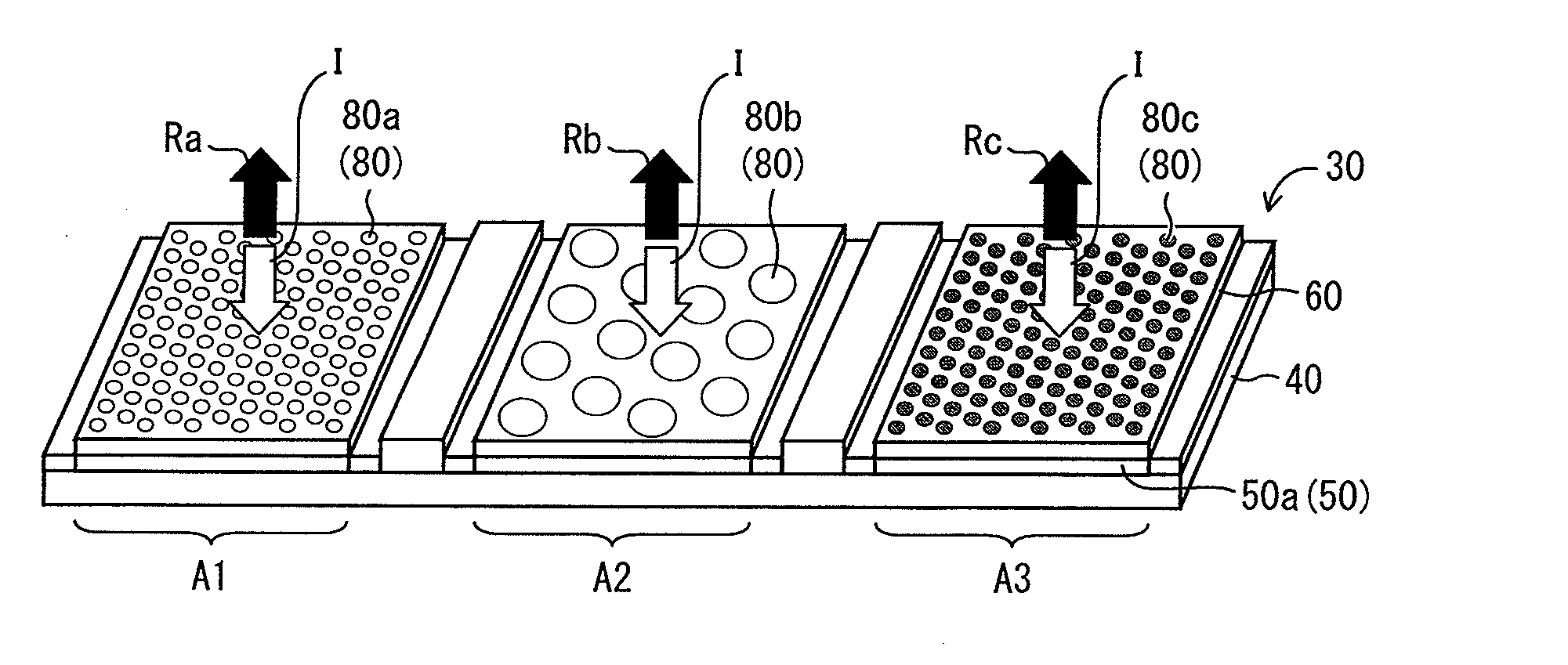
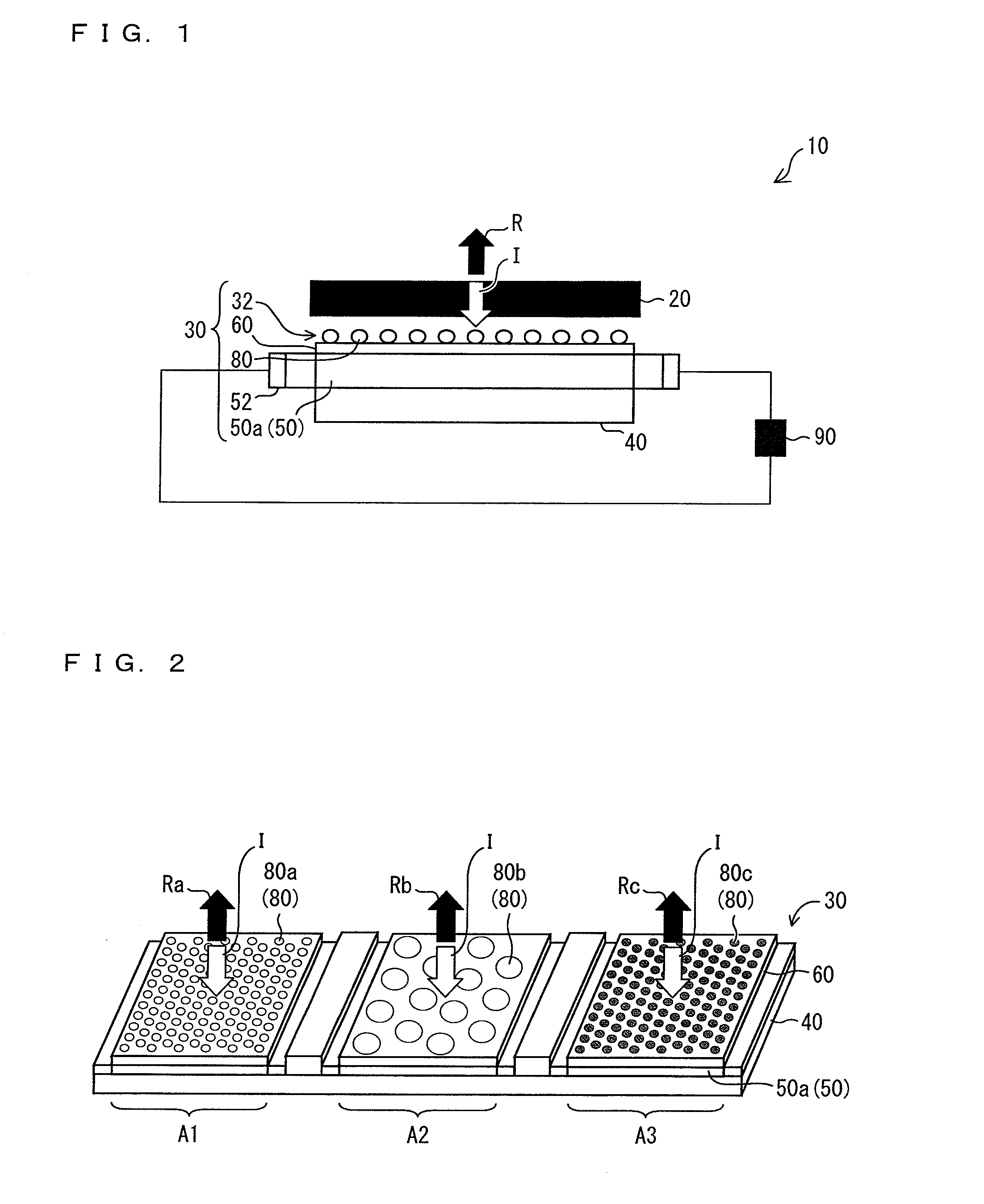
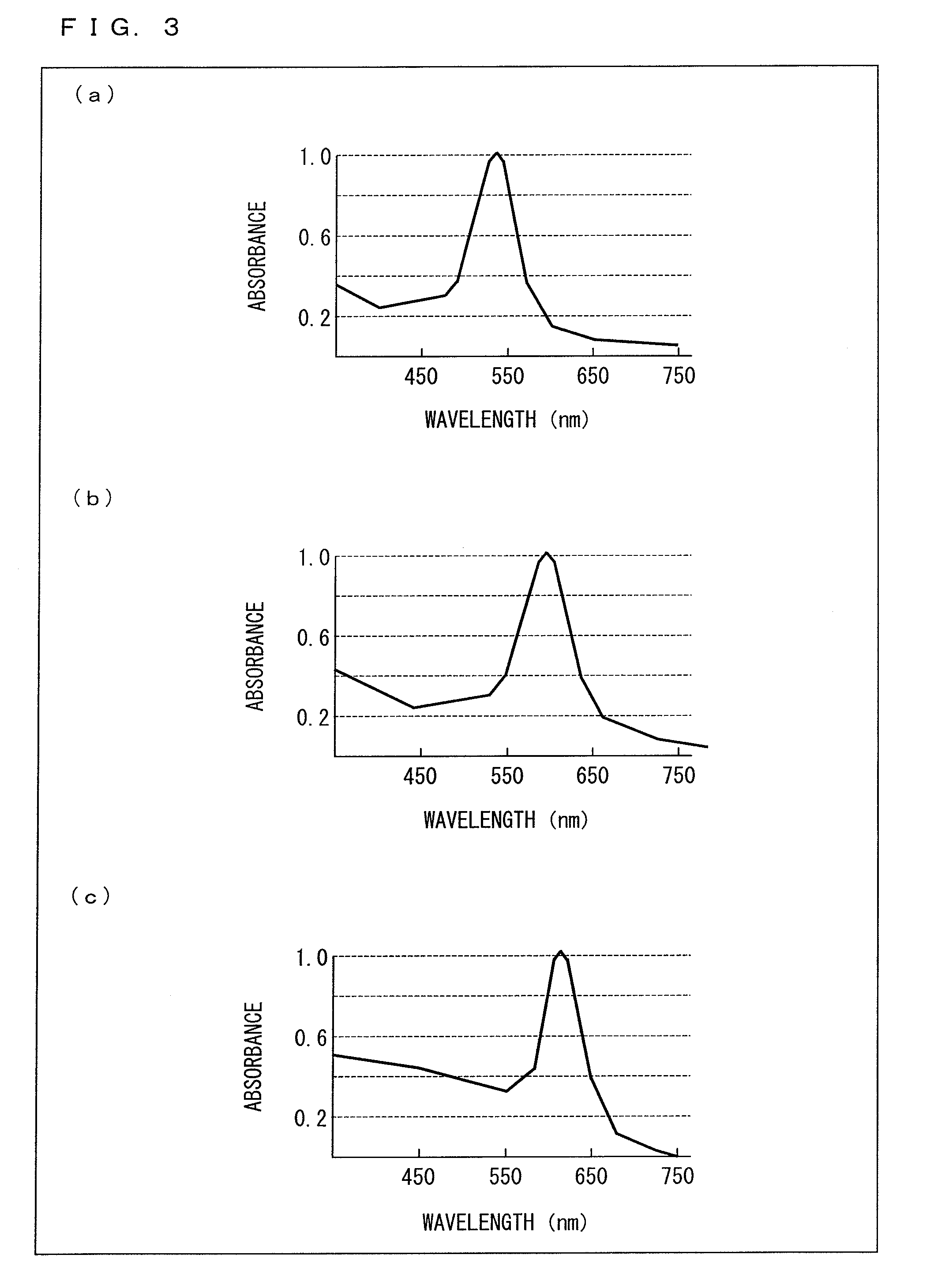
[0054]The following describes an embodiment of the present invention, with reference to FIGS. 1 through 3.

[0055](Schematic Arrangement)

[0056]As illustrated in FIG. 1, a reflection type display device 10 of the present embodiment includes a light shutter 20, a main part 30, a band-pass filter 40 which serves as a reflector, and a storage battery 90. The main part 30 is constituted mainly by a plasmon resonance layer 32 which serves as a metal nanoparticle dispersion layer in which metal nanoparticles 80 are dispersed (including being deposited, being arrayed, etc.), and a solar cell layer 50 provided close to the plasmon resonance layer 32.

[0057]The light shutter 20, the main part 30, and band-pass filter 40 are provided so as to overlap in planar view. The storage battery 90 is electrically connected with the main part 30, more specifically, connected with the solar cell layer 50 in the main part 30. The following describes these members.

[0058](Main Part)

[0059]The following first de...

embodiment 2

[0125]The following describes another embodiment of the reflection type display device 10 of the present invention. The following explanation mainly deals with differences between the reflection type display device 10 of Embodiment 1 and a reflection type display device 10 of the present embodiment, and omits descriptions of common points therebetween.

[0126]The reflection type display device 10 of the present embodiment is different from the reflection type display device 10 of Embodiment 1, with regard to how to deposit (disperse) the metal nanoparticles 80 on the oxidized film layer 60.

[0127]That is, according to the Embodiment 1, an ethanol solution in which the metal nanoparticles 80 are dispersed is applied onto the oxidized film layer 60, and then the ethanol is evaporated so that the metal nanoparticles 80 are deposited on the oxidized film layer 60.

[0128]In the case of the reflection type display device 10 of the present embodiment, in contrast, the metal nanoparticles 80 ar...

embodiment 3

[0140]The following describes another embodiment of the reflection type display device 10 of the present invention, with reference to FIGS. 4 and 5.

[0141]For convenience of explanation, members having the same functions as those of the members in the drawings described in Embodiment 1 are given common reference signs, and descriptions of such members are omitted below.

[0142]Metal nanoparticles 80 to be deposited in a green display region A2 of the reflection type display device 10 of the present embodiment are different from those of the reflection type display device 10 of Embodiment 1.

[0143]That is, in the case of the reflection type display device 10 of Embodiment 1, one type of metal nanoparticles, i.e., the metal nanoparticles of gold having a particle diameter of 40 nm are deposited in the green display region A2 as the green metal nanoparticles 80b.

[0144]In contrast, in the case of the reflection type display device 10 of the present embodiment, two types of metal nanopartic...


PUM

PropertyMeasurementUnit
particle diameteraaaaaaaaaa

Abstract

A reflection type display device (10) includes: a plasmon resonance layer (32) in which metal nanoparticles (80) are dispersed; a band-pass filter (40); a light shutter (20); and a silicon solar cell layer (50a) being provided close to the plasmon resonance layer (32). The band-pass filter (40) and the light shutter (20) are provided so as to overlap the plasmon resonance layer (32) in planar view. The reflection type display device (10) performs display in such a manner that: the metal nanoparticles (80) allow light having a specific wavelength to pass through; the light is then reflected by the band-pass filter (40); and the light shutter (20) adjusts an intensity of the light thus reflected.

Description

REFERENCE TO RELATED APPLICATIONS[0001]This application is the national stage under 35 USC 371 of International Application No. PCT / JP2010 / 001939, filed Mar. 18, 2010, which claims priority from Japanese Patent Application No. 2009-198450, filed Aug. 28, 2009, the entire contents of which are incorporated herein by reference.FIELD OF THE INVENTION[0002]The present invention relates to a reflection type display device which achieves a high light utilization efficiency. Specifically, the present invention relates to a reflection type display device which makes it possible to reuse, by use of a solar cell, light unnecessary for display.BACKGROUND OF THE INVENTION[0003]Conventionally proposed as reflection type display devices capable of color display are, e.g., a color electronic paper and a reflection type display device of an IMOD (Interferometric Modulator) type utilizing reflection interference.[0004]FIG. 10 is a cross-sectional view illustrating a schematic arrangement of the colo...

Claims


Application Information

Patent Timeline
Patent Type & Authority Applications(United States)
IPC IPC(8): G02F1/01G02B26/02B82Y20/00
CPCB82Y20/00G02B5/008G02B5/26G02B26/02G02F2202/36G02F1/133514G02F1/133553G02F2001/133521G02B2207/101G02F1/133521
Inventor YASHIRO, YUHJISHIGETA, HIROAKI
Owner SHARP KK
Learn More