Electrochemically driven pump
a technology of electrochemical drive and pump, which is applied in the direction of positive displacement liquid engine, separation process, instruments, etc., can solve the problems that the design and construction materials of the pump are the most expensive components of the lc system
- Summary
- Abstract
- Description
- Claims
- Application Information
AI Technical Summary
Benefits of technology
Problems solved by technology
Method used
Image
Examples
example 1
[0057]This example uses a Pump 1 embodiment of ECP.
[0058]The ECP Pump 1 was constructed using components similar to those used in Dionex SRS suppressors. The general construction of Dionex SRS suppressors is similar to the embodiment of the electrolytic suppressor described in FIG. 2 of U.S. Pat. No. 5,352,360. Parameters relevant to the components and their functions are set out in U.S. Pat. No. 5,352,360 and are incorporated herein by reference.
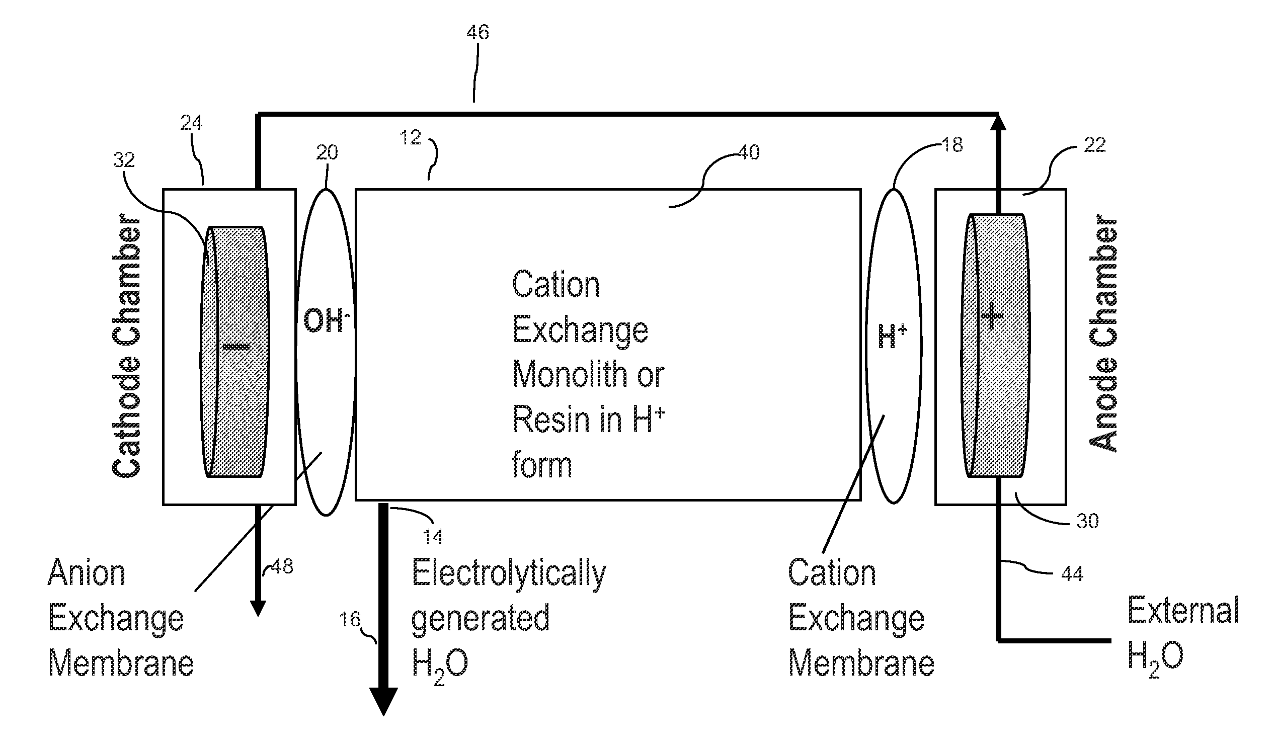
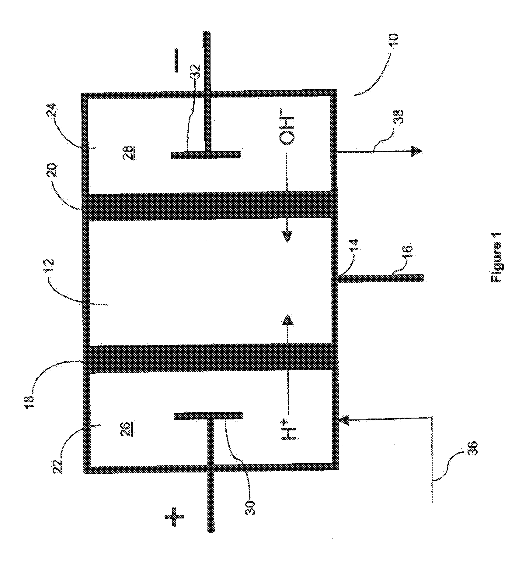
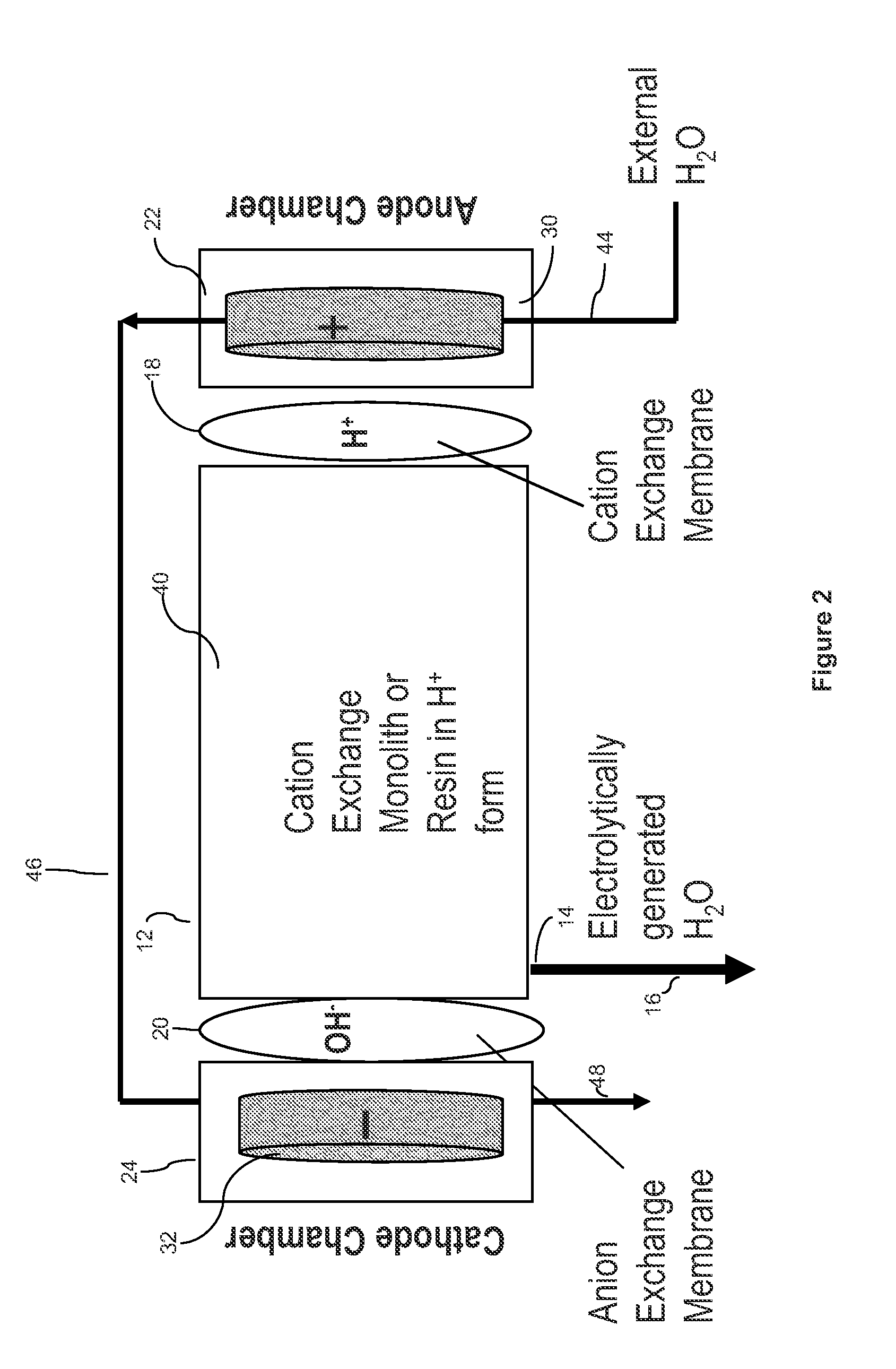
[0059]In the ECP Pump 1 shown in FIG. 1, the anion SRS suppressor (ASRS) chromatography effluent channel was used as the central water generator compartment 12 by plugging its inlet port. The water generator compartment was partially bounded by the chromatography effluent gasket defining a central cavity. A flow-through sulfonated cation exchange screen was disposed in the cavity. Two ion exchange membrane sheets were mounted to extend along opposite sides of central water generator compartment and defined the outer perimeter of the central...
example 2
Examples of the ECP in Operation
[0076]Pump 1: Flow rate versus current at atmospheric pressure.
[0077]Table 1 summarizes the results of measuring the flow rate of Pump 1 at six different currents with the pump discharging to atmosphere.
[0078]The second column lists the measured flow rates while the third column gives the faradaic flow rates (see “The Pumping Mechanism”) calculated for each current. By dividing the measured flow rate by the faradaic flow rate one obtains a figure for the total number of moles of water (faradaic plus hydration plus electroosmotic) transported per faraday (column 4)
TABLE 1Measured FlowCurrentMeasured Flow RateFaradaic Flow Rate,Rate / FaradaicmAμL / minμL / minFlow Rate100.4230.1123.78200.8560.2243.82301.280.3363.81401.720.4483.84502.160.563.85602.630.6723.91
[0079]FIG. 6 shows the linear dependence of flow rate on applied current and suggests a simple method for controlling the output of the ECP.
[0080]Pump 2: Flow rate versus current and applied backpressure....
PUM
| Property | Measurement | Unit |
|---|---|---|
| back pressures | aaaaa | aaaaa |
| internal diameter | aaaaa | aaaaa |
| volume | aaaaa | aaaaa |
Abstract
Description
Claims
Application Information
 - R&D
- Intellectual Property
- Life Sciences
- Materials
- Tech Scout
- Unparalleled Data Quality
- Higher Quality Content
- 60% Fewer Hallucinations
Browse by: Latest US Patents, China's latest patents, Technical Efficacy Thesaurus, Application Domain, Technology Topic, Popular Technical Reports.
© 2025 PatSnap. All rights reserved.Legal|Privacy policy|Modern Slavery Act Transparency Statement|Sitemap|About US| Contact US: help@patsnap.com


