
Apparatus and method for managing hot cell devices

a technology of hot cell devices and apparatus, applied in the field of communication technologies, can solve the problems of energy waste, high energy consumption, and high interference and iot, and achieve the effect of saving energy

Active Publication Date: 2012-05-31
SAMSUNG ELECTRONICS CO LTD
View PDF13 Cites 15 Cited by
  • Summary
  • Abstract
  • Description
  • Claims
  • Application Information

AI Technical Summary

Benefits of technology

[0017]To address the above-discussed deficiencies of the prior art, it is a primary aspect of the present invention to address at least the above mentioned problems and / or disadvantages and to provide at least the advantages described below. Accordingly, an aspect of the present invention is to provide an apparatus and a method for managing hot cell devices, which can save energy.

Problems solved by technology

If a cell base station in these hot areas also works normally when there is no user capacity, much electric energy will be uselessly consumed, this is obviously conflicted with the sustainable development target.
The larger the user capacity and the closer the proximity to the hot cell device, the more serious the interference and the higher the IoT.
However, users in the cell providing basic radio coverage can be switched to one or part of the hot cells, and there may be no user capacity in other hot cells, thereby when all hot cell devices are open will lead to energy wasting.
Secondly, some hot cells have larger coverage, and others have smaller coverage.
However in the ordinary course of events, the number of users to be switched to a hot cell is not larger at the beginning, and the capabilities of whole cell are all opened in the prior art conflicts with the target of energy saving.
If the hot cell devices are configured to gradually open device capabilities, when a larger numbers of users in the cell providing basic radio coverage need to be switched to hot cells, requirement of the cell providing basic radio coverage (called as basic coverage cell hereinafter for simplification) can not be satisfied.
It is obvious that, the conventional methods for managing hot cell devices can cause energy wasting.

Method used

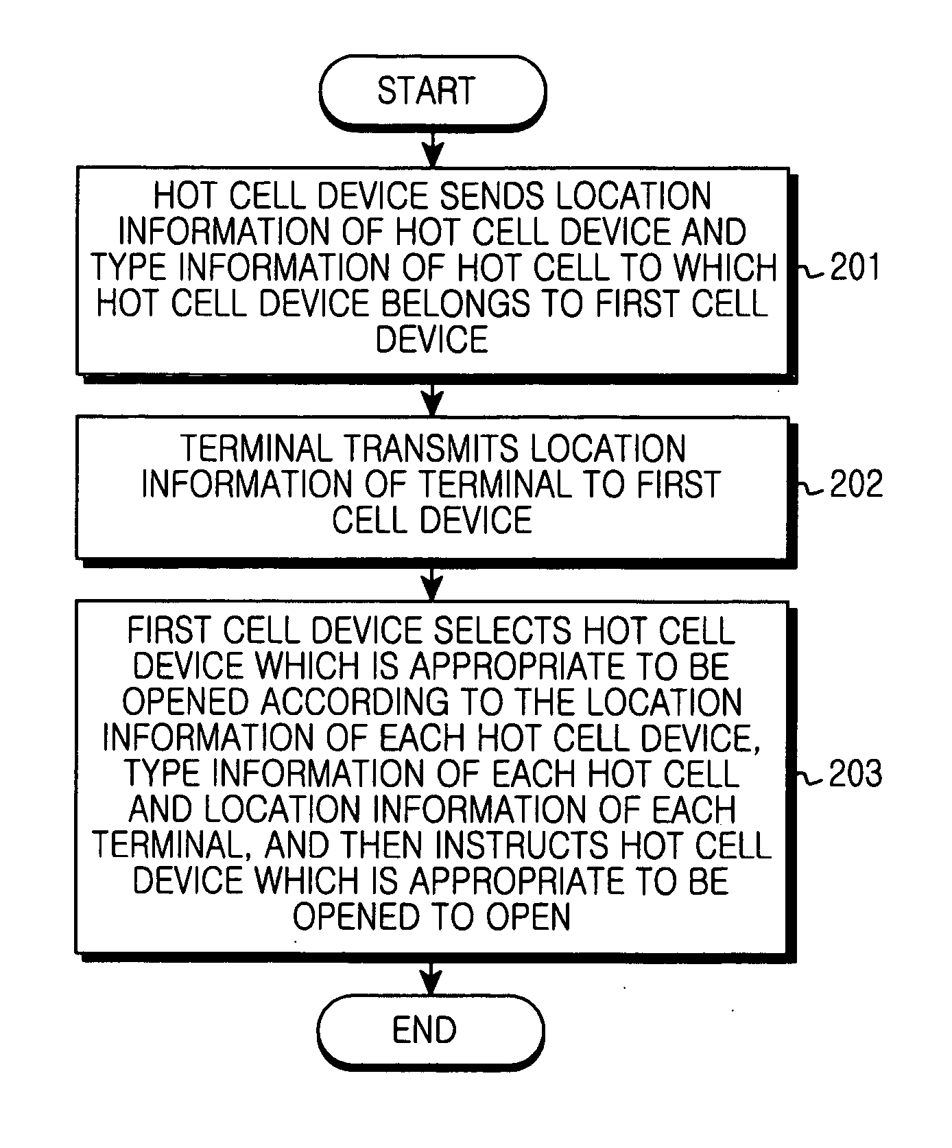
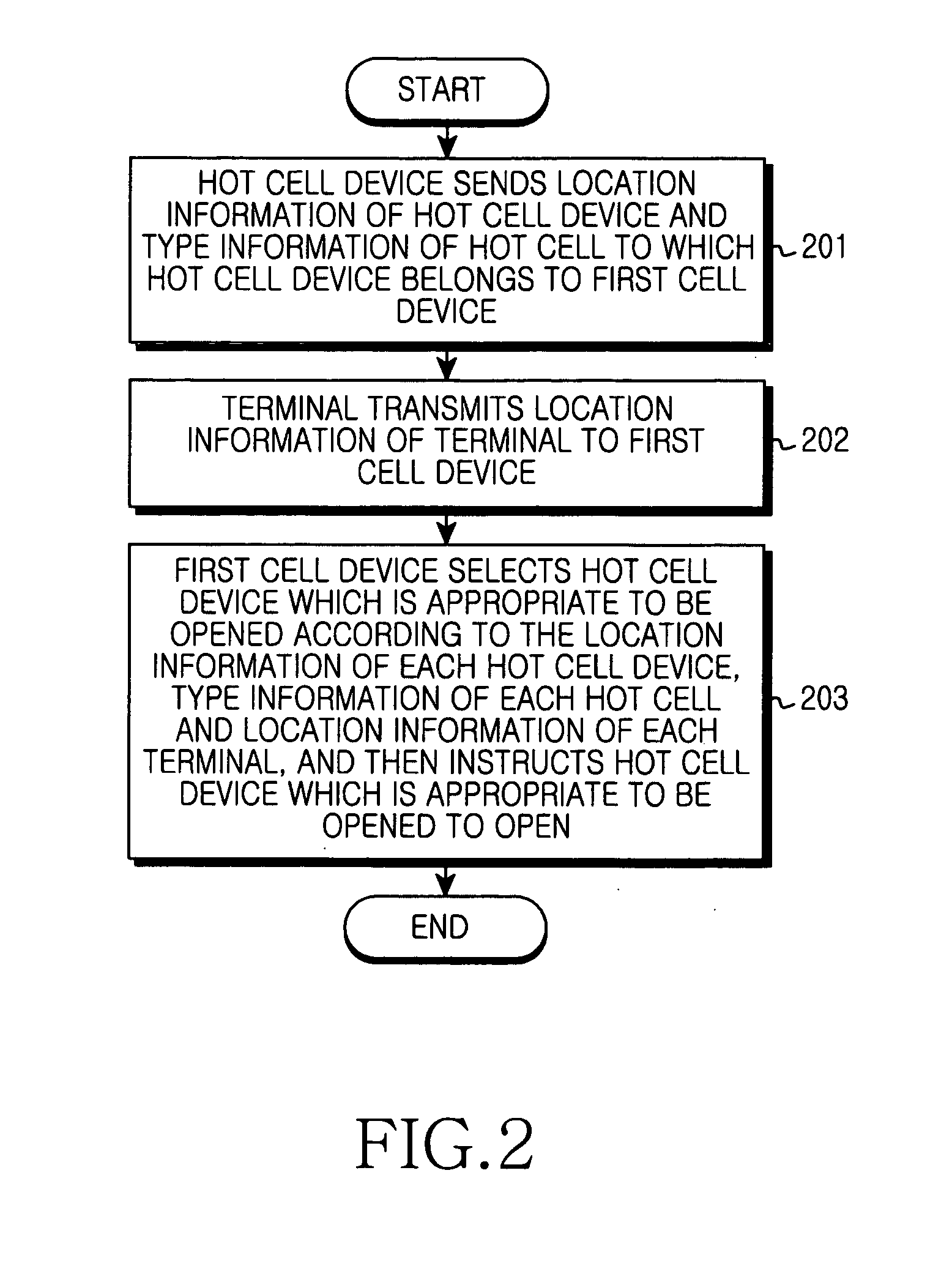

Image

  • Apparatus and method for managing hot cell devices
  • Apparatus and method for managing hot cell devices
  • Apparatus and method for managing hot cell devices

Examples


first embodiment

[0044]A first embodiment will be described.

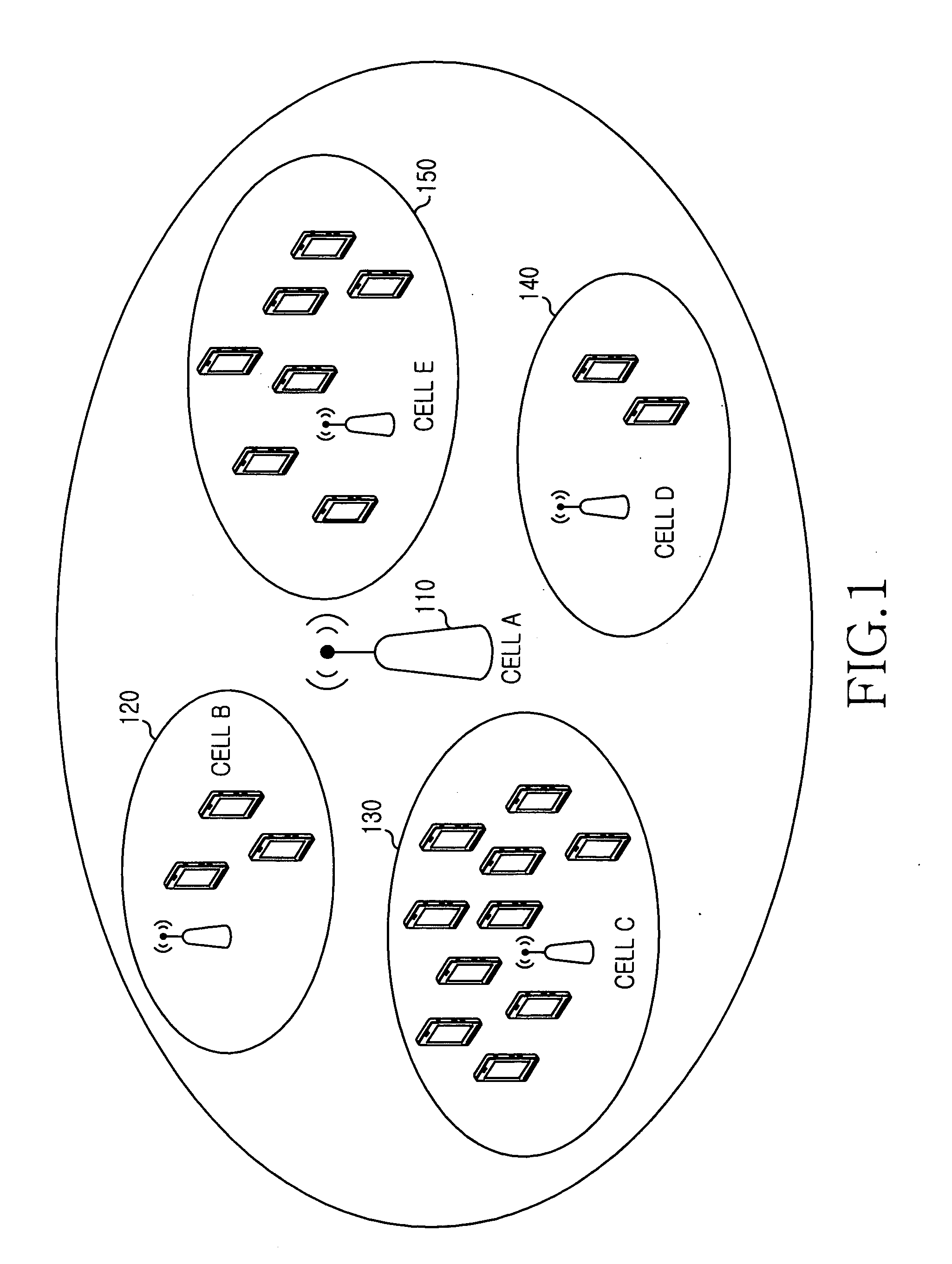
[0045]The embodiment applies to the system as shown in FIG. 1. In the system, cell A 110 is a basic coverage cell, and provides basic radio coverage for a certain area; cell B 120, cell C 130, cell D 140 and cell E 150 are hot cells in the signal coverage of cell A 110, and are cells deployed for further enhancing system capacity. Each hot cell can be closed when the user capacity is smaller, and be opened when the user capacity is larger. Cell A can adopt conventional radio interface technologies, such as Wideband Code Division Multiple Access (WCDMA) and GSM, or cell A 110 can also adopt LTE access system or other future access system. The hot cell can be LTE access system, or other access system.

[0046]When a hot cell device is closed, the hot cell device notifies a basic coverage cell device of location information of the hot cell device and type information of the hot cell. Alternatively, the hot cell device can notify the basic coverag...

second embodiment

[0059]A second embodiment will be described.

[0060]The embodiment applies to the system as shown in FIG. 1. In the embodiment, the hot cell notifies the location information of each hot cell device and type information of the hot cell when X2 interface is established. The embodiment will be described hereinafter in detail with reference to the accompanying drawing.

[0061]FIG. 4 illustrates a method for managing hot cell devices in accordance with the second embodiment of the present invention. The method includes the following processes.

[0062]In step 401, a hot cell device transmits an X2 establishment request message to the basic coverage cell device. The X2 establishment request message includes a unique identifier of the hot cell. The X2 establishment request message also includes geographical location of the hot cell device. The geographical location can be information of longitude or latitude. The X2 establishment request message also includes cell type of the hot cell, and the c...

third embodiment

[0075]A third embodiment will be described.

[0076]The embodiment applies to the system as shown in FIG. 1, and the embodiment will be described hereinafter in detail with reference to the accompanying drawing.

[0077]FIG. 5 illustrates a method for managing hot cell devices in accordance with the third embodiment of the present invention. The method includes the following processes.

[0078]Referring to FIG. 5, in step 501, capacity of a hot cell is in an idle state for a period of time, in order to save electricity, a device of the hot cell (also referred to as a hot cell device) closes transmitting function of air interface, and transmit a cell closing message to the basic coverage cell device, to notify the basic coverage cell device of close state of the hot cell. The cell closing message contains a unique identifier of the hot cell to be closed. The cell closing message also contains geographical location of the hot cell device. The geographical location can be information of longitu...


PUM


Abstract

A method for managing hot cell devices includes receiving at least one of location information of at least one hot cell device, type information of at least one hot cell, location information of at least one terminal and uplink signal energy of at least one terminal measured by a hot cell device. The method also includes determining a hot cell device to be opened using the at least one of the location information of at least one hot cell device, the type information of at least one hot cell, the location information of at least one terminal and the uplink signal energy of at least one terminal. In addition, the method includes transmitting a message instructing the hot cell device to open.

Description

CROSS-REFERENCE TO RELATED APPLICATION(S) AND CLAIM OF PRIORITY[0001]The present application is related to and claims the benefit under 35 U.S.C. §119(a) of a Chinese patent application filed in the Chinese Intellectual Property Office on Nov. 26, 2010 and assigned Serial No. 201010575852.5, the entire disclosure of which is hereby incorporated by reference.TECHNICAL FIELD OF THE INVENTION[0002]The present invention relates to communication technologies, and more particularly, to method for managing hot cell devices.BACKGROUND OF THE INVENTION[0003]At present, sustainable development is a long-term target of human beings, enhancing energy efficiency and reducing energy consumption is becoming an increasingly important topic. In the communication field, how to enhance energy efficiency of devices and terminals is a key part for saving energy.[0004]FIG. 1 illustrates an area repeated covered by several cells in prior art. The same area as shown in FIG. 1 is repeated covered by multipl...

Claims


Application Information

Patent Timeline
IPC IPC(8): H04W24/00
CPCH04W48/06H04W84/045Y02B60/50H04W52/0206H04W64/003H04W92/20Y02D30/70H04W24/04H04W72/21
Inventor WANG, HONGLIANG, HUARUI
Owner SAMSUNG ELECTRONICS CO LTD
Learn More