Write Head Having Recessed Magnetic Material In Gap Region
a write head and gap region technology, applied in the field of magnetic write heads, can solve the problems of affecting the data integrity of the system, unintended erasure of adjacent tracks on the disk, etc., and achieve the effect of limiting the width of material and reducing the magnetic influence of adjacent tracks
- Summary
- Abstract
- Description
- Claims
- Application Information
AI Technical Summary
Benefits of technology
Problems solved by technology
Method used
Image
Examples
1st embodiment
1st Embodiment
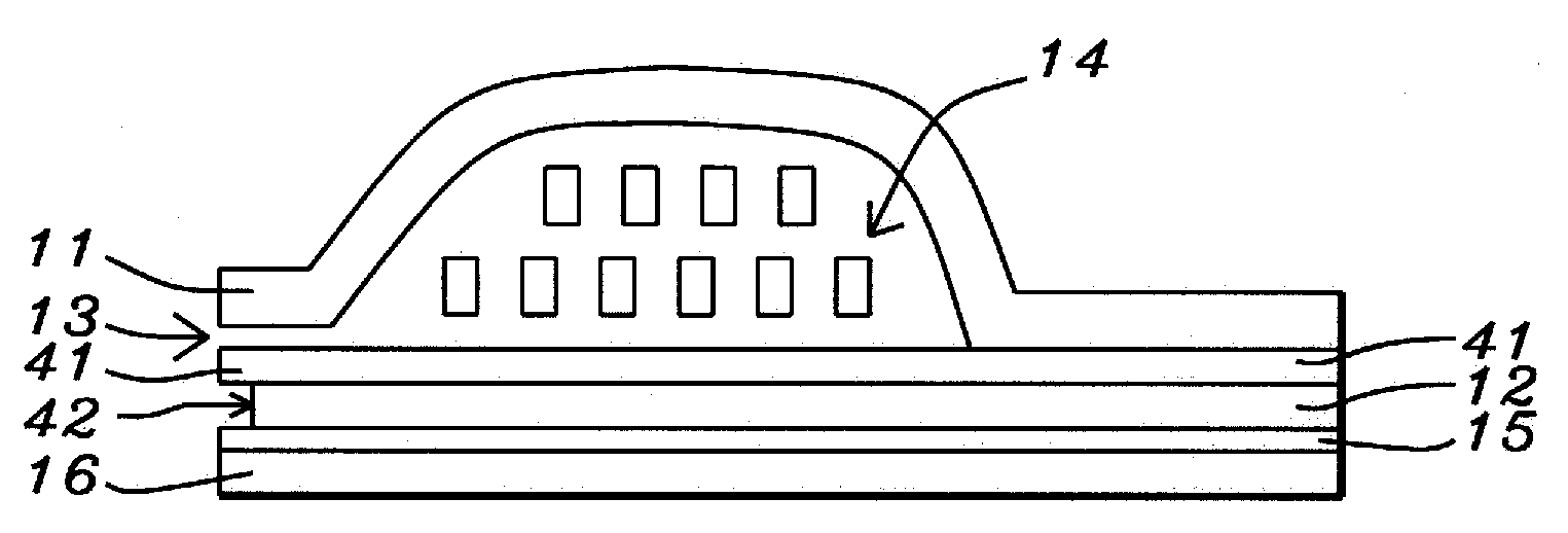
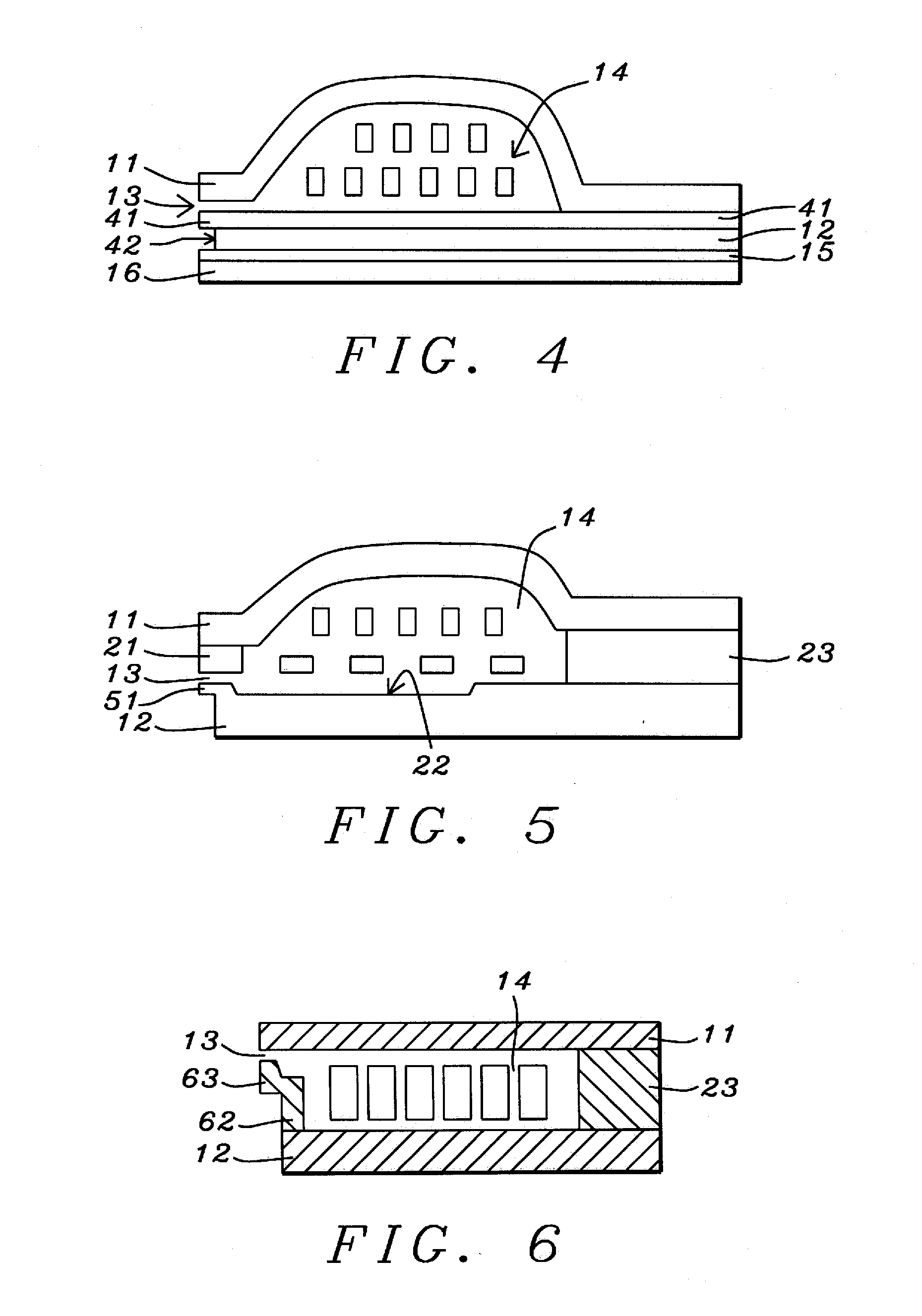
[0026]Referring now to FIG. 4, we show there a structure that is similar to the one shown in FIG. 1, but modified in accordance with the teachings of the disclosed structure. As before, upper pole 11 and lower pole 12 enclose, between them, field coil 14. The key novel feature is ledge 41 of magnetic (high permeability) material that extends outwards away from the main body of lower pole 12. The outer edge of ledge 41 has the same width as, and is in alignment with, the outer edge of top pole 11 so that write gap 13 lies between them and said widths define the track width TW. As a result, most of bottom pole 12 is set back some distance from the ABS and so has relatively little magnetic interaction with the disk surface. FIG. 7 is an isometric view that illustrates the spatial relationships between top pole 11 and bottom poles 41 and 12.
[0027]For purposes of simplification, FIG. 4 has been drawn as though ledge 41 is a cantilever. In actuality, a layer of insulation is...
2nd embodiment
2nd Embodiment
[0028]FIG. 5 shows a structure similar that seen in FIG. 2. As before, there is a general similarity to the first embodiment illustrated in FIG. 4 with the addition of stitched secondary top pole 21 and shallow trench 22. The key departure is the addition to the structure of ledge 51, which analogous to ledge 41 of the first embodiment, and serves the same purpose. FIG. 7 is an isometric view that illustrates the spatial relationships between top pole 21 and bottom poles 51 and 12 while FIG. 13 is a plan view of this structure.
3rd embodiment
3rd Embodiment
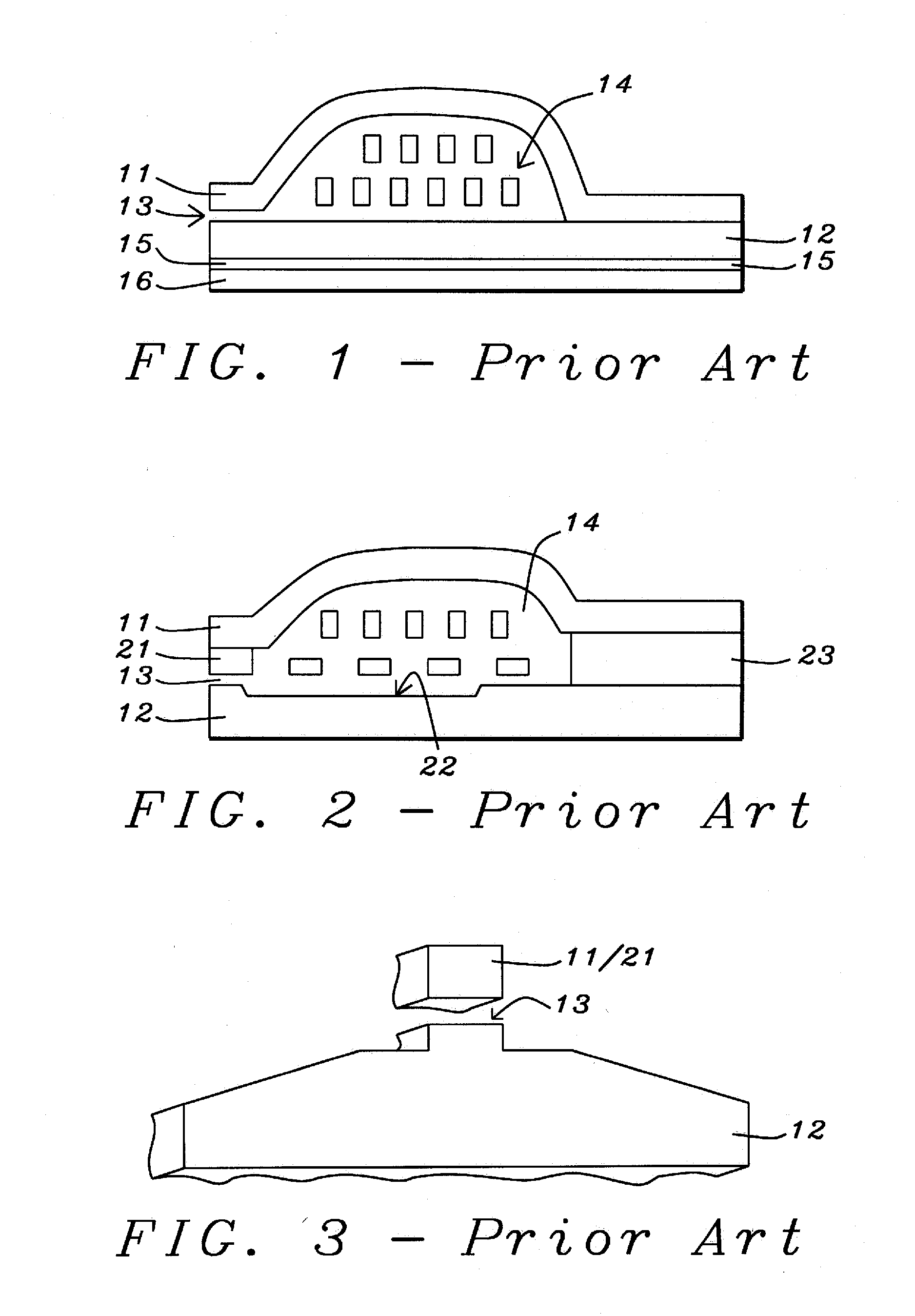
[0029]This variation of the basic structure is sometimes preferred because certain parts, such as pole 11, are easier to manufacture. By going to a somewhat thicker inter-pole connector 23 and using a single turn for field coil 23, top pole 11 can be flat rather than humped, as in the previous two embodiments. The bottom pole in this case is composed of two layers, 62 and 12, which, in prior art versions of this variant (not shown), would extend from bottom pole 12 all the way to write gap 13.
[0030]As seen in FIG. 6, in the disclosed structure the secondary bottom pole is in two parts 62 and 63. Part 62 extends upwards from bottom pole 12 but not all the way to write gap 13. This leaves room for second part 63 which, in addition to extending the rest of the way up to the write gap, also extends laterally away from part 62 so as to be aligned with the ABS end of top pole 11. As a result, the lower part of the secondary bottom pole and all of the main bottom pole 12 are ...
PUM
| Property | Measurement | Unit |
|---|---|---|
| length | aaaaa | aaaaa |
| length | aaaaa | aaaaa |
| separation distance | aaaaa | aaaaa |
Abstract
Description
Claims
Application Information
 - R&D
- Intellectual Property
- Life Sciences
- Materials
- Tech Scout
- Unparalleled Data Quality
- Higher Quality Content
- 60% Fewer Hallucinations
Browse by: Latest US Patents, China's latest patents, Technical Efficacy Thesaurus, Application Domain, Technology Topic, Popular Technical Reports.
© 2025 PatSnap. All rights reserved.Legal|Privacy policy|Modern Slavery Act Transparency Statement|Sitemap|About US| Contact US: help@patsnap.com


