Liquid Crystal Display Device and Driving Method Thereof

a technology of liquid crystal display and driving method, which is applied in the direction of electric digital data processing, instruments, computing, etc., can solve the problems of increasing the heat dissipation temperature of the data driver, the effect of csc not reaching a satisfactory level, and the rapid increase of power consumption

Active Publication Date: 2012-05-31
LG DISPLAY CO LTD
View PDF10 Cites 32 Cited by
  • Summary
  • Abstract
  • Description
  • Claims
  • Application Information

AI Technical Summary

Benefits of technology

[0021]Accordingly, the present invention is directed to an LCD device and a driving method thereof,...

Problems solved by technology

However, according to the inversion driving mode, as a swing width of the data voltage supplied to data lines is increased and much current occurs in a data driver whenever a polarity of the data voltage is changed, problems occur in that a heating temperature of the data driver is increased and power consumption is increased rapidly.
However, the effect of the CSC fails to reach a satisfactory level.
However, although power consumption can be reduced by the aforementioned schemes, since the same power as that consumed for an active interval is consumed even for a vertical blank interval where no image is output between frames, the LCD device according to the related art has a problem in that unnecessary power consumption still occurs.
Meanwhile, as described above...

Method used


Image

  • Liquid Crystal Display Device and Driving Method Thereof
  • Liquid Crystal Display Device and Driving Method Thereof
  • Liquid Crystal Display Device and Driving Method Thereof

Examples


first embodiment

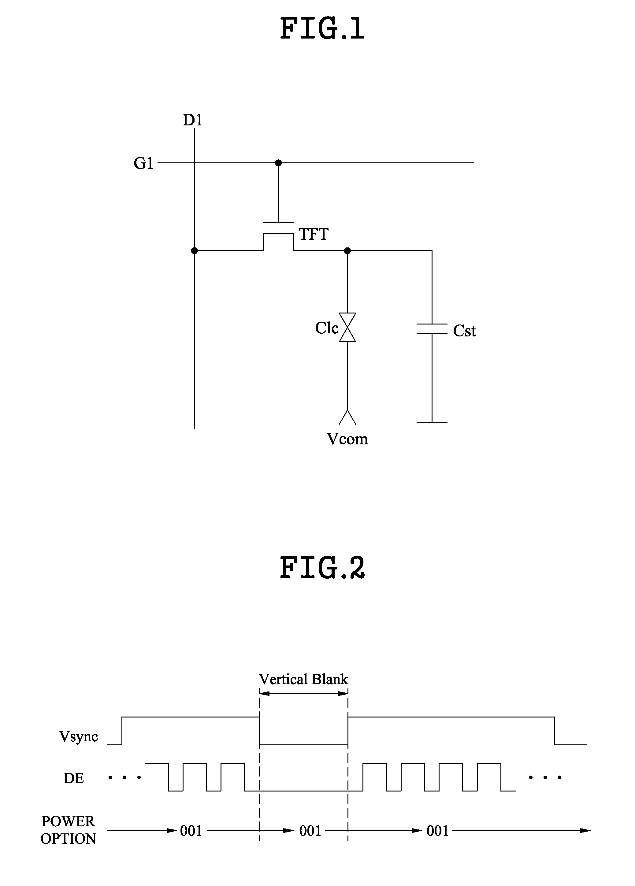
[0065]In the first embodiment, the timing controller 114 defines the vertical blank interval and active interval, and directly generates the internal vertical sync signal. The timing controller 114 is required to first know the start point of the vertical blank interval of the internal vertical sync signal, for directly generating the internal vertical sync signal. That is, since the timing controller 114 may determine the input time of the data enable signal as the start point of the vertical blank interval of the internal vertical sync signal, it is an important issue to detect the start point of the vertical blank interval that is continued after the active blank.

[0066]A first method where the timing controller 114 detects the start point of the vertical blank interval of the internal vertical sync signal Vsync′ is as follows.

[0067]When the data enable signal is inputted from the external system, this is determined as the start point of the active blank of the internal vertical s...

second embodiment

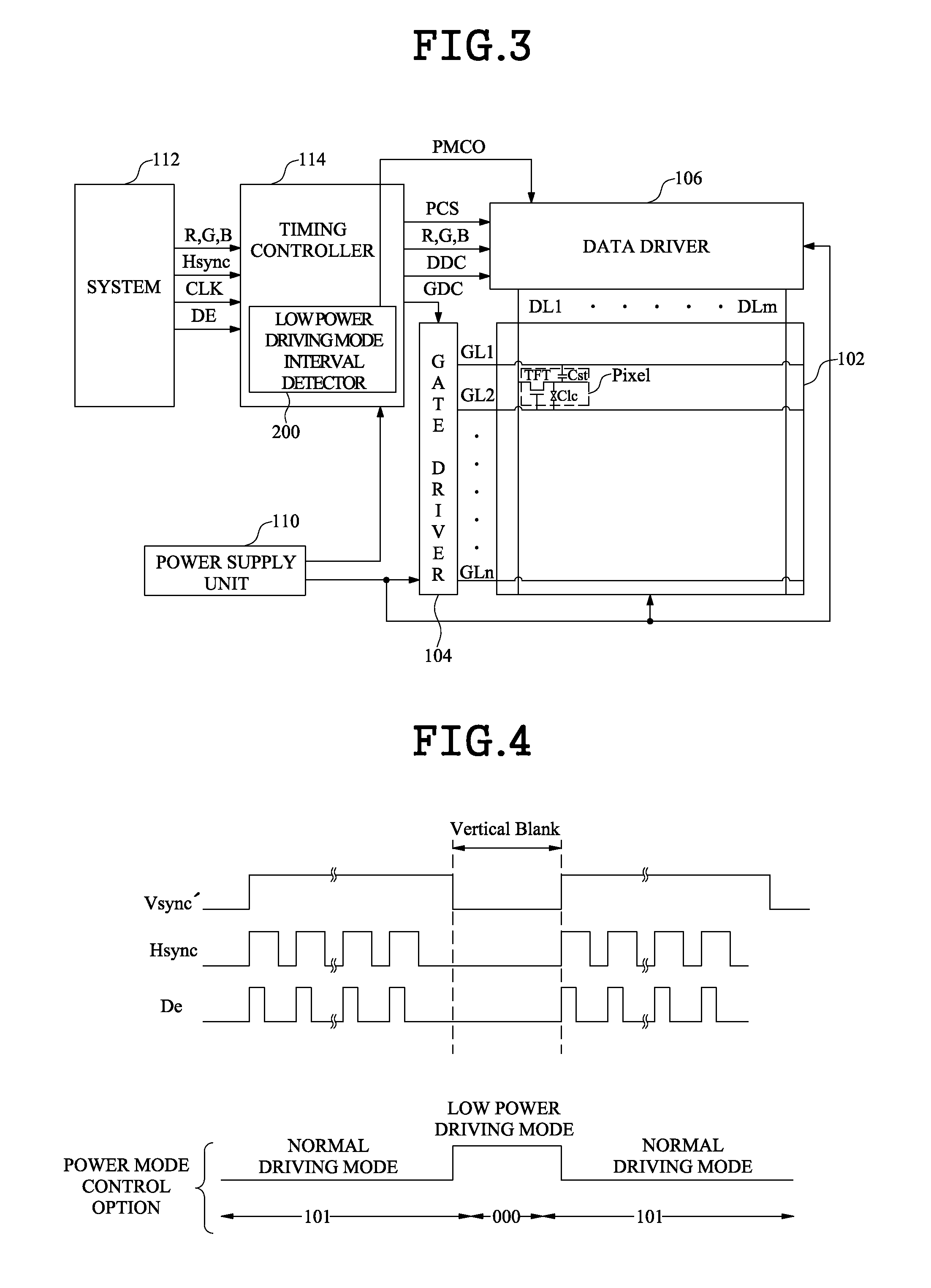
[0084]In the second embodiment, the timing controller 114 does not separately generate the internal vertical sync signal Vsync′ but uses the vertical sync signal Vsync received from the external system.

[0085]In the first embodiment, the timing controller 114 defines the vertical blank interval with the data enable signal DE and horizontal sync signal Hsync received from the external system, thereby directly generating the internal vertical sync signal Vsync′. In the second embodiment, however, the vertical sync signal Vsync received from the external system is being used for detecting the low power driving mode interval.

[0086]In the second embodiment, therefore, since a pre-generated vertical sync signal Vsync is being used, the vertical blank interval is not required to be separately defined as in the first embodiment, and thus, various methods are required for setting the low power driving mode interval within the vertical blank interval.

[0087]The following description will be mad...


PUM


Abstract

An LCD device and a driving method thereof are disclosed. The LCD device includes a data driver, a detection unit, and a power mode control option generation unit. The data driver controls a consumption power of an output buffer which outputs an image data signal to a liquid crystal display panel. The detection unit detects a low power driving mode interval for driving the data driver at a first consumption power. The power mode control option generation unit transfers a second power mode control option to the data driver during an interval other than the low power driving mode interval, and transfers a first power mode control option to the data driver during the low power driving mode interval.

Description

CROSS REFERENCE TO RELATED APPLICATIONS[0001]This application claims the benefit of the Korean Patent Application No. 10-2010-0120342 filed on Nov. 30, 2010 and the Korean Patent Application No. 10-2011-0098769 filed on Sep. 9, 2011, which are hereby incorporated by reference for all purposes as if fully set forth herein.BACKGROUND OF THE INVENTION[0002]1. Field of the Invention[0003]The present invention relates to a Liquid Crystal Display (LCD) device and a driving method thereof, and more particularly, to an LCD device and a driving method thereof, which reduce the power consumption of a data driver.[0004]2. Discussion of the Related Art[0005]An LCD device controls the light transmittances of liquid crystal cells to display an image, according to a video signal.[0006]FIG. 1 is an exemplary diagram illustrating an equivalent circuit of a pixel included in a liquid crystal display panel of a general liquid crystal display.[0007]Since an active matrix type LCD device actively contro...

Claims


Application Information

Patent Timeline
IPC IPC(8): G09G3/36G09G5/00
CPCG09G2330/021G09G3/3688
Inventor JI, HA YOUNGKIM, JIN SUNGKIM, MIN KI
Owner LG DISPLAY CO LTD
Why Eureka
Try Eureka