[0008]In an advantageous embodiment of the invention, it is provided that the first bearing is lubricated by fuel under pressure; and that the first bearing is in hydraulic communication with both the fuel
feed line and the fuel return line. This means that on one side of the first bearing, approximately the same pressure prevails as on the compression side of the prefeed pump, while the other side of the first bearing is in
pressure equilibrium with the virtually pressureless fuel return line. As a result, the first bearing necessarily experiences a flow through it of fuel, and thus adequate
lubrication and cooling of the first bearing is assured at all operating points.
[0009]In a further advantageous feature of the invention, a first flow limiting device is provided, which is connected in series with the first bearing.
[0010]The first flow limiting device serves to keep the fuel flow, which flows through the first bearing, within predetermined limits. In
mass production of high-pressure fuel pumps, it can happen, because of production variations and wear at the first bearing, that the thickness of the
lubrication gap and hence the fuel flow through the bearing and its
bearing capacity will vary within very wide limits. This means that if the tolerance situation is unfavorable, the
bearing capacity of the first bearing and its cooling and
lubrication by the fuel are not adequate at all operating points. If the first flow limiting device according to the invention is now connected in series with the first bearing, it is possible because of the very narrow production tolerance with which the first flow limiting device can be produced to adjust the fuel flow by means of the first bearing. As a result, the aforementioned production variations have only a slight effect on the
bearing capacity, so that even given an unfavorable tolerance situation, the bearing capacity of the first bearing is assured at all operating points of the high-pressure fuel pump.
[0011]The flow limiting device limits the fuel flow that flows through the bearing. As a result, in unfavorable tolerance situations of the bearing, the demands made of the prefeed pump are reduced.
[0012]The object stated at the outset is attained, in a high-pressure fuel pump for a
fuel injection system of an
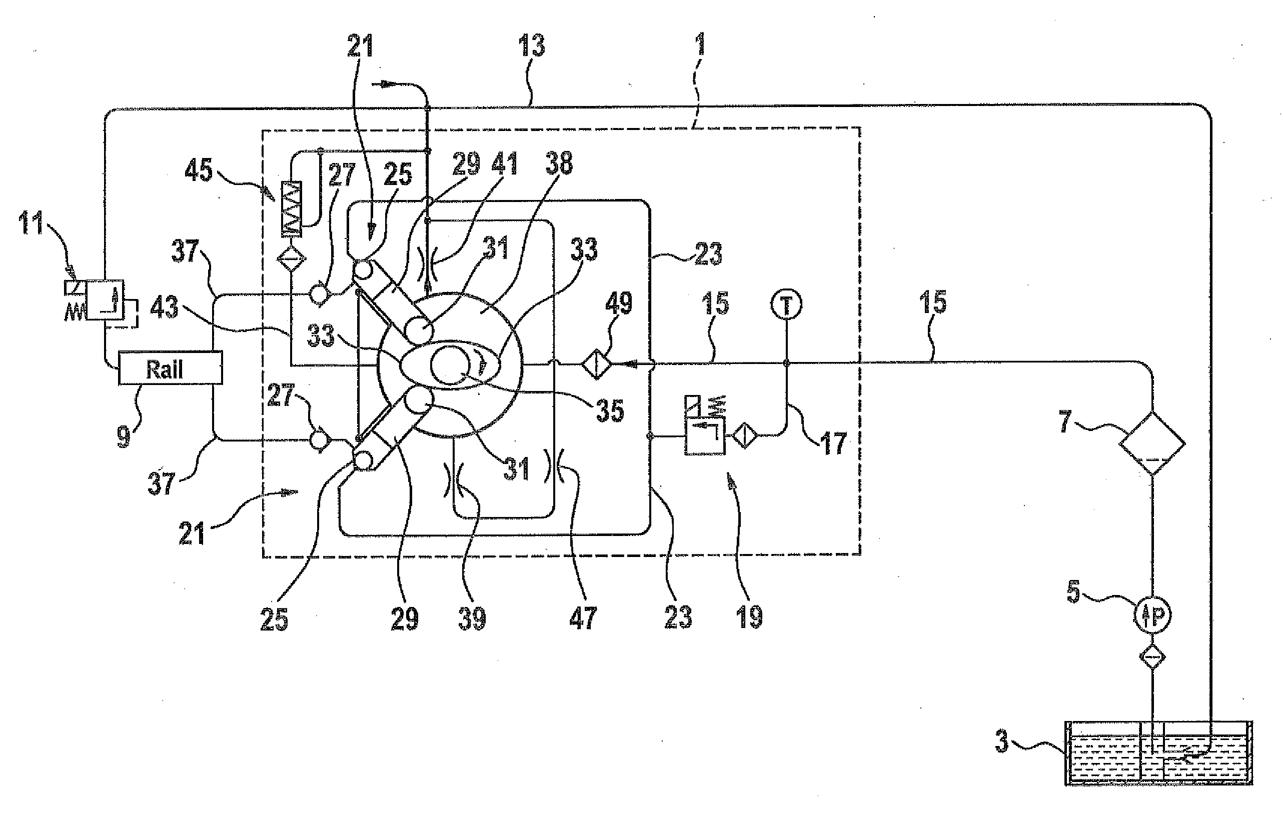
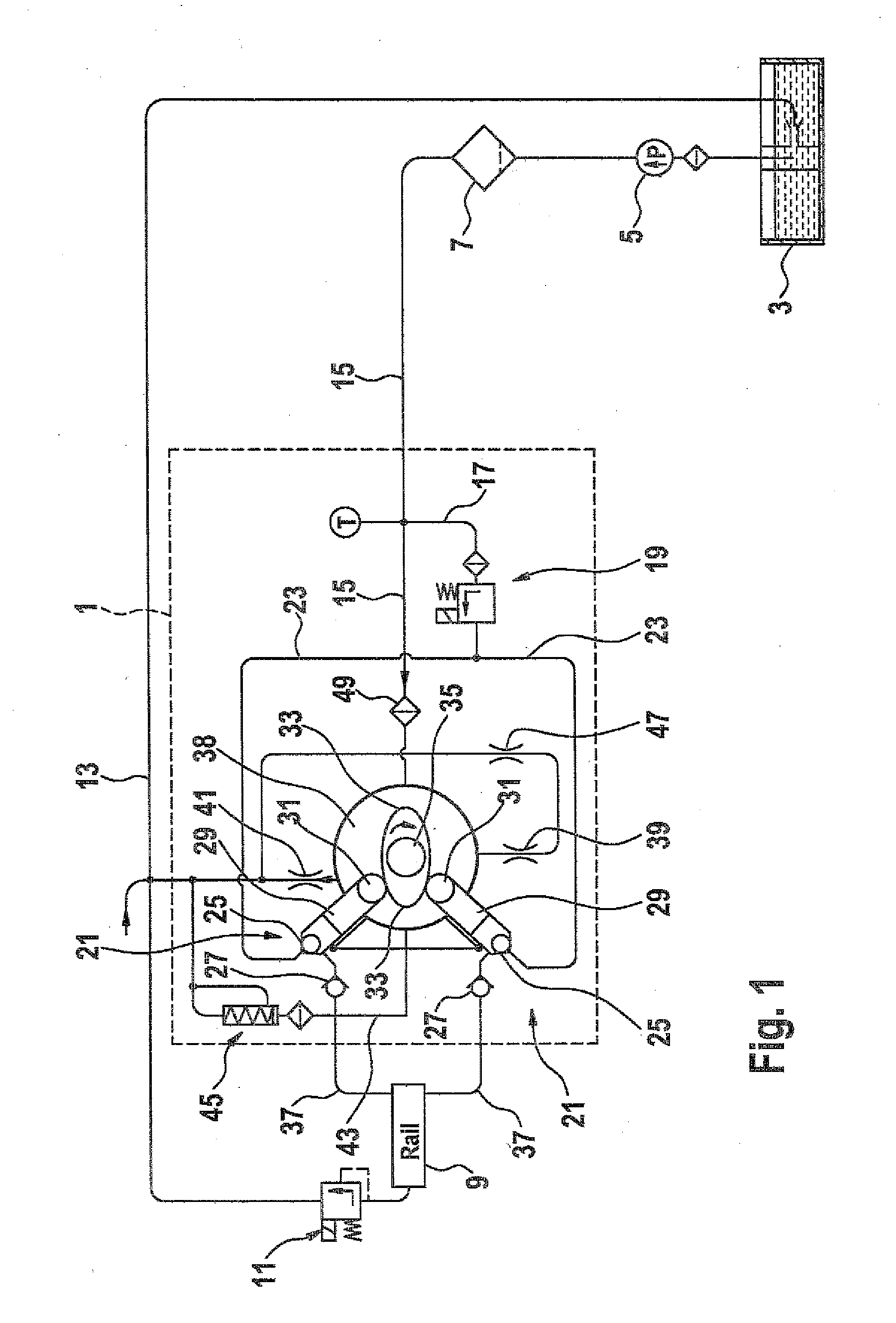
internal combustion engine, having a pump housing, having a drive shaft with the drive shaft supported in the pump housing by a first bearing and a second bearing, having at least one pump element disposed radially relative to the drive shaft, having a fuel feed line, where a prefeed pump pumps fuel into the fuel feed line, having a fuel return line, having a metering unit for regulating the pump capacity of the pump element or elements, and having a pressure regulating valve, in that the first bearing is lubricated by fuel under pressure; that the first bearing is in hydraulic communication with both the fuel feed line and the fuel return line; a first flow limiting device is provided; and that the first flow limiting device is connected in series with the first bearing; and that between the pump housing and the fuel return line, a bypass
throttle restriction is provided.
[0013]In this exemplary embodiment of a high-pressure fuel pump of the invention, it is possible by the suitable
adaptation of the first flow limiting device and the bypass
throttle restriction to assure in a simple and effective way that an adequate quantity of fuel will flow through the first bearing, thus assuring the cooling and lubrication of this bearing at all operating points.
[0005]In a high-pressure fuel pump for a
fuel injection system of an
internal combustion engine, having a pump housing, having a drive shaft with the drive shaft supported in the pump housing by a first bearing and a second bearing, having at least one pump element disposed radially relative to the drive shaft, having a fuel feed line, where a prefeed pump pumps fuel into the fuel feed line, having a fuel return line, having a metering unit for regulating the pump capacity of the pump element or elements, and having a pressure regulating valve, this object is attained in that the pressure regulating valve is disposed in the fuel return line.
[0015]A factor in favor of disposing the metering unit between the prefeed pump and the high-pressure fuel pump in the fuel feed line is that with this arrangement, the fuel flowing into the high-pressure region of the high-pressure fuel pump will not have first flowed through the pump housing, so that any chips or other particles may be present there cannot get into the high-pressure fuel region.
[0016]An
advantage of disposing the metering unit in the fuel return line is that the entire fuel quantity pumped by the prefeed pump is available at every
operating point for cooling and lubricating the pump housing or the drive shaft of the high-pressure fuel pump as well as the associated bearings. As a result, the bearing capacity of the low-pressure region of the high-pressure fuel pump of the invention is increased still further.
[0017]Alternatively, it is possible to dispose the first flow limiting device either upstream or downstream of the first bearing. Which disposition will be preferred in an individual case depends on the circumstances and
peripheral conditions of the individual case.
[0018]In a further augmentation of the high-pressure fuel pumps of the invention, it may furthermore be provided that the second bearing is lubricated by fuel under pressure, and that the second bearing is in hydraulic communication with both the fuel feed line and the fuel return line.
[0019]Moreover, a second flow limiting device may be provided, which is disposed upstream or downstream of the second bearing. The advantages of the forced lubrication of the second bearing and of the second flow limiting device correspond essentially to the advantages mentioned above, in conjunction with the first bearing and the first flow limiting device.
[0023]Advantageously, the fuel connection discharges into an interior of the pump housing.
[0024]In a fuel injection system for an internal
combustion engine having a prefeed pump, a tank, a high-pressure fuel pump, a
common rail, and at least one
injector, the advantages of the invention are attained if the high-pressure fuel pump is a high-pressure fuel pump as defined by one of the foregoing claims.
[0025]Alternatively, the prefeed pump may be driven by the engine or by an
electric motor.

