Switching Device

Active Publication Date: 2012-05-24
ABB (SCHWEIZ) AG
View PDF17 Cites 2 Cited by
  • Summary
  • Abstract
  • Description
  • Claims
  • Application Information

AI Technical Summary

Benefits of technology

[0008]The object of the present invention is an improved switching device that is easy and quick to assemble and disassemble. A further object of the invention is a switching device with a simple design that requires a small number of screw joints for holding the components of the switching device together. A further object of the invention is a switching device that requires few assembling steps to be assembled or disassembled.
[0011]The at least one attachment arrangement, comprising the receiving member and the insert member, holds the base member, the conductor members, the middle member and the stationary part of the switch member together in a desired arrangement. The receiving member is formed in the base member, the middle member and the protruding member. The receiving member receives the insert member so that the receiving member and the insert member engage and form an attachment between the base member, the middle member and the protruding part of the switch member. By means of the at least one attachment arrangement in the base member, the middle member and the protruding member, the structure of the device is simplified so that the assembling or disassembling of the device requires a reduced number of attachment arrangements and a reduced number of assembling steps compared to prior art. Thus, the production cost of the device is reduced.
[0012]The base member acts as a fundament for the conductor members. The middle member acts as a lid for the pair of conductor members. Thereby, the conductor members of the pair of conductor members are protected from foreign objects that may cause a short circuit of the conductor members.
[0023]By means of the positioning member, the protruding part is positioned in the certain position on the middle member. The asymmetry in the attachment arrangement assures that the protruding part is only positionable in the certain position on the middle member. Thereby, it is assured that the switch member is positioned in a desired position on the middle member. Thus, possible errors during assembling the switch member on the base member are prevented.
[0026]The base member and the middle member, in cooperation with each other, have the function of holding the conductor members in a certain position and electrically isolate the conductor members of the pair of conductor members from each other. The base member together with the middle member creates a cover around the pair of conductor members protecting the pair of conductor members from the surrounding environment around the device.

Problems solved by technology

A problem with manufacturing switching devices is that the assembly of the components is time consuming due to the large number of screw joints.
Moreover, switching devices need to be disassembled for maintenance and replacement of components after certain period of operation.
A problem with the presented electrical contactor is that the two arms increase the complexity and the requirement on dimensional tolerance of the contactor.

Method used


Image

  • Switching Device
  • Switching Device
  • Switching Device

Examples


Embodiment Construction

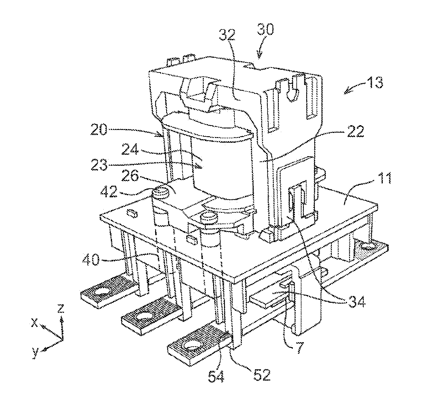
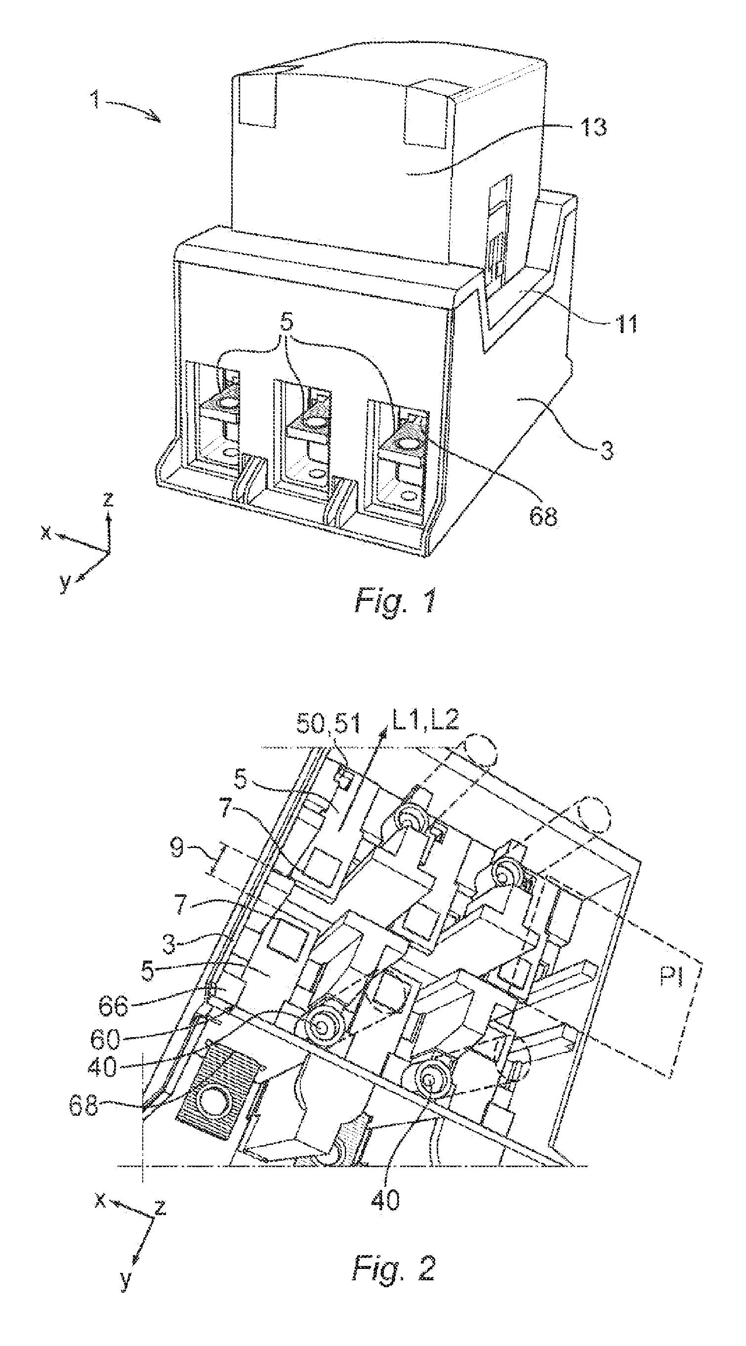
[0037]FIG. 1 shows an example of a switching device 1 according to the invention seen from the exterior in an assembled state. The device 1 comprises a base member 3, three pairs of conductor members 5, a middle member 11 and a switch member 13. The base member 3 and the middle member 11 are preferably made of a non-conductive material such as a polymeric material, wherein the base member 3 and the middle member 11 preferably are manufactured by means of injection molding. The pair of conductor members 5 comprises an electrical conductive material, such as a copper alloy.

[0038]Two opposing sides of the base member 3 are provided with apertures 68 that receive the conductor members 5. The switch member 13 is seen with a casing that covers the interior. Each conductor member 5 is adapted to be connected to an external electric power source by means of a connection assembly such a cable clamp, cable lug, etcetera. For example, the switching device 1 is adapted to be connected to and co...


PUM


Abstract

A mechanical switching device including a base member, at least one pair of elongated conductor members mounted on the base member, each conductor member including a conductor end, wherein the conductor ends of the pair of conductor members are separated by a gap, a middle member mounted on the base member, a switch member including a stationary part and a movable part, the movable part including a conductor bridge. The stationary part includes a protruding member protruding away from the direction of displacement of the conductor bridge, wherein the base member, the conductor members, the middle member and the stationary part of the switch member are attached together by means of at least one attachment arrangement formed in the base member, the middle member and the protruding member.

Description

CROSS-REFERENCE TO RELATED APPLICATIONS[0001]The present application is a continuation of pending International patent application PCT / EP2009 / 060082 filed on Aug. 4, 2009 which designates the United States and the content of which is incorporated herein by reference.FIELD OF THE INVENTION[0002]The present invention relates to a mechanical switching device comprising a base member, at least one pair of elongated conductor members mounted on the base member, each conductor member comprising a conductor end, wherein the conductor ends of the pair of conductor members are separated by a gap, a middle member mounted on the base member, a switch member comprising a stationary part and a movable part, the movable part comprising a conductor bridge that is adapted to be displaced in a direction towards or away from the conductor members between a first position and a second position, wherein in the first position the two conductor ends lack electrical connection and in the second position t...

Claims


Application Information

Patent Timeline
IPC IPC(8): H01H50/02H01H9/02
CPCH01H50/042H01H2050/446H01H50/546H01H50/045
Inventor ERIKSSON, LARSJOHANSSON, MATS
Owner ABB (SCHWEIZ) AG
Why Eureka
Try Eureka