
Hinge Pivot Mount Assembly

Inactive Publication Date: 2012-05-17
ASSA ABLOY LTD
View PDF1 Cites 2 Cited by
  • Summary
  • Abstract
  • Description
  • Claims
  • Application Information

AI Technical Summary

Benefits of technology

[0006]By causing the two movable pivots of what are essentially adjacent parallel hinges to move together, the top part of a sash is prevented from falling outwards. Indeed, the use of the connector results in both parallel hinges moving at the same time to the same extent, thereby resulting in almost perfect parallel opening of a vent.
[0013]Typical slider blocks were able to move freely along a track and provided good support for a sash. However, now that much heavier sashes are being supported, it has been necessary to invent a new form of mounting block, and this has resulted in the present invention which uses roller balls.
[0015]The mounting block preferably includes a body and a skin overlaying the body to prevent the body from contacting the track in use. This is particularly useful when the body is manufactured from metal and the skin is a plastics skin, since not only does the plastics skin result in less friction between the mounting block and the track, but the plastics skin can readily incorporate cut out regions to accommodate the roller balls. Thus, the roller balls can abut both the metal track and the metal body of the mounting block, to transfer the weight of the sash directly therebetween.
[0021]The cam surface is preferably circular and offset from the axis of the shaft of the pivot pin. Further, the diameter of the circle defining the cam surface is preferably larger than the diameter of the shaft of the pivot pin, thereby allowing a significant amount of movement of a sash mounted on the parallel opening hinge to be achieved. Essentially, rotation of the cam surface adjusts the position of the track carrying the sash relative to the remainder of the parallel hinge.
[0024]As mentioned above, the central pivot joint between two links of a parallel opening hinge can provide a region of too much free play, which can be detrimental to the functioning of the parallel opening hinge. Thus, the present invention further provides a pivot between two links of a hinge, the pivot including a fastener holding the links together, and bush (also well known as a bushing) acting on the fastener to define spacing between the links. By including the bush, which is ideally a good fit through the links, a pivot arrangement is produced wherein axial free play along the fastener can be minimised. As a result, smoother operation of the pivot can result, thereby improving the opening of a parallel hinge, for example.
[0028]The bush is preferably rigid and, acts as a bearing for the two links. Phosphor bronze is a very good bearing material, which also has good strength and rigidity. Other suitable materials can, of course, alternatively be used. As will be appreciated, a washer is ideally used between the two links outside the bush to prevent wear between the links. Hence, the bush must have sufficient length to accommodate this washer, which is preferably nylon or other suitable material.

Problems solved by technology

Although these systems work, it has been noted that the weight of a sash can cause a certain amount of dropping and falling out of the upper part of the sash relatively to the fixed frame.
This can result in the vent opening out of parallel and being unsightly, and is certainly not ideal.
Once again, this is not ideal and essentially spoils the smooth running of the hinge system whether it is driven by manual operation or an electric motor.
It has also been noted that too much free play in a central pivot joint between two links of a parallel opening hinge can also reduce the smooth operation of the hinge system.

Method used


Image

  • Hinge Pivot Mount Assembly
  • Hinge Pivot Mount Assembly
  • Hinge Pivot Mount Assembly

Examples


Embodiment Construction

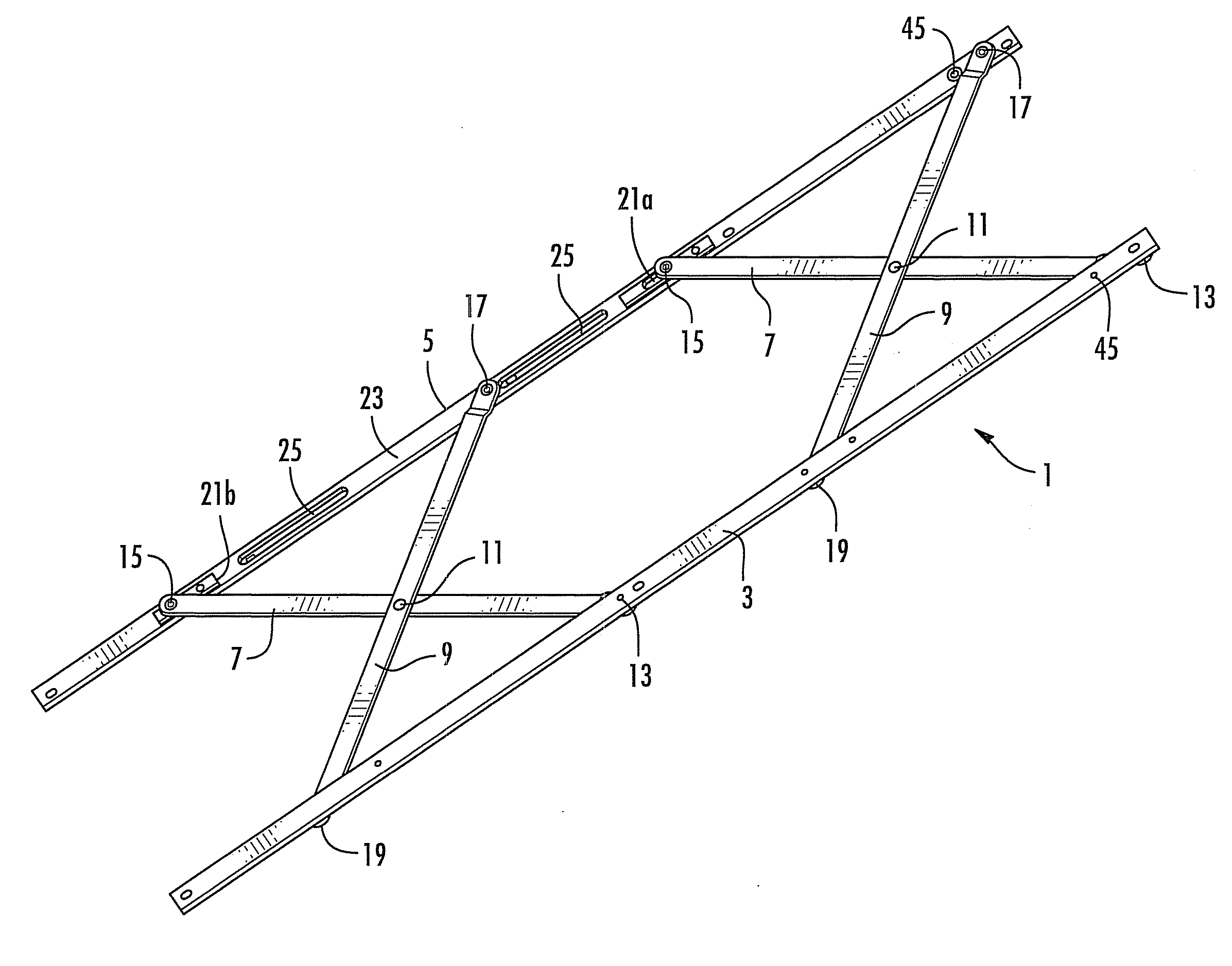
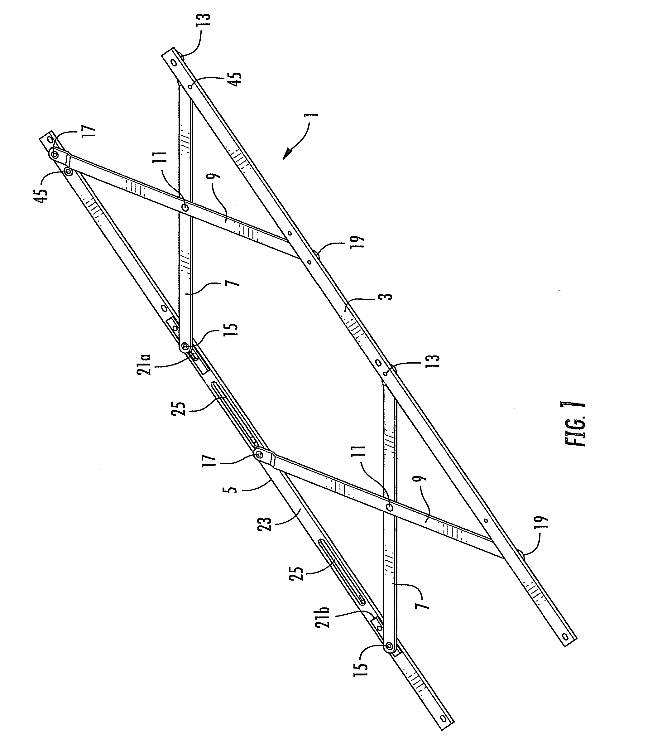
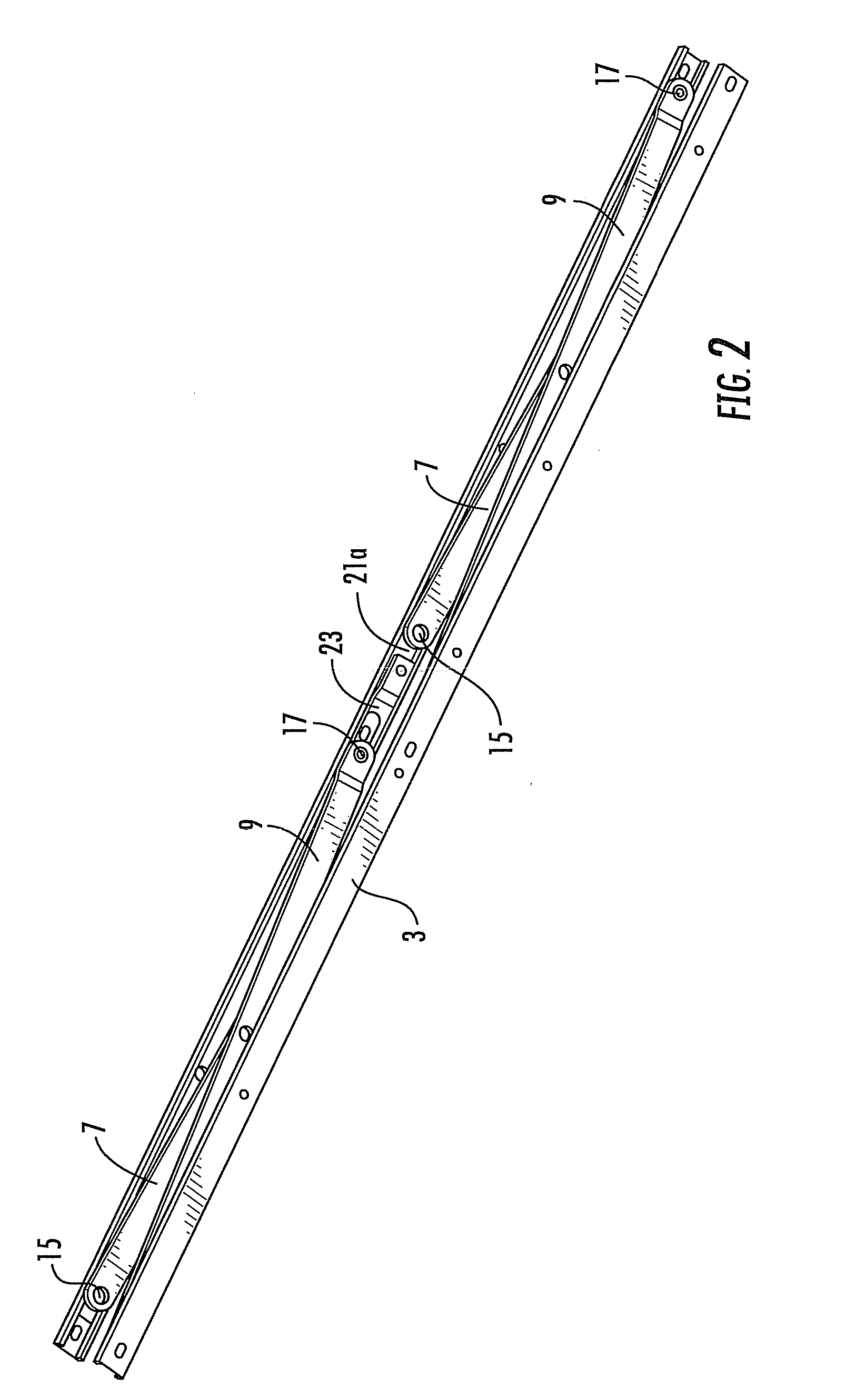
[0038]With reference to FIGS. 1 and 2 of the accompanying drawings, a parallel opening hinge system 1 is shown. As will be seen, the hinge system effectively incorporates two parallel hinge arrangements in a single product. The new parallel hinge includes a pair of parallel tracks 3, 5 each having essentially a C-shaped cross-section with a base and two side walls having inwardly facing flanges substantially parallel to the base. The hinge 1 further includes two pairs of crossing links 7, 9, wherein each pair of crossing links 7, 9 is pivotally connected at a pivot 11 and to each track 3, 5. The links 7 are attached to track 3 at fixed pivot points 13 and to track 5 at movable pivot points 15. Similarly, the links 9 are attached to track 5 at fixed pivot points 17 and to track 3 at movable pivot points 19. Thus, as the parallel tracks 3, 5 are moved together or apart, the movable pivots 15, 19 travel along the tracks whereas the fixed pivots 13, 17 remain fixed.

[0039]As will be seen...


PUM


Abstract

A parallel opening hinge includes tracks pivotally connected crossing links, wherein each pair of crossing links is mounted to the tracks via a fixed pivot and a movable pivot in each track. A connector joins two movable pivots in a track such that the movable pivots move together. Improved opening of a parallel opening vent can thereby result. A pivot mount for a link of the hinge includes a support block and a pivot pin engaging the support block, wherein the pivot pin includes a cam surface for abutting a link of a hinge in use to move the link relative to the support block.

Description

CROSS-REFERENCE TO RELATED APPLICATIONS[0001]This application claims the benefit of and is a continuation of U.S. application Ser. No. 12 / 293,007, filed Sep. 15, 2008, which was filed through a National Phase Entry from International Patent Application PCT / GB2007 / 000817, having an international filing date of Mar. 12, 2007 which itself claims the benefit of GB0605364.9, filed Mar. 16, 2006 and GB0613380.5, filed Jul. 5, 2006, the disclosures of which are hereby incorporated by reference herein in their entireties, and all commonly owned.FIELD OF THE INVENTION[0002]The present invention generally relates to hinges for vents and parts therefor, and in particular relates to parallel opening hinges and improvements thereto.BACKGROUND OF THE INVENTION[0003]Parallel opening hinges are well known, as illustrated by way of example to European Patent No. 0968349 for a vent, the disclosure of which is herein incorporated by reference in its entirety.[0004]When a heavy window sash, say perhaps...

Claims


Application Information

Patent Timeline
IPC IPC(8): E05D5/12
CPCE05D15/30Y10T16/5476E05F11/24F16C11/04E05D15/00E05Y2900/148E05D15/34E05D15/1013Y10T16/5474Y10T16/54Y10T16/558Y10T403/32073Y10T16/553Y10T16/547E05D15/44E05F11/10E05F11/12E05D15/46
Inventor LAMBERT, JOHN F.
Owner ASSA ABLOY LTD
Learn More