Vehicle lamp

A technology for lamps and vehicles, which is applied in the direction of headlights, road vehicles, vehicle parts, etc. It can solve the problems of torque transmission damage, loose driving rod, and reduced operability of light adjustment, so as to prevent wear, improve reliability, and improve operational effect

Active Publication Date: 2019-01-18
KOITO MFG CO LTD
View PDF13 Cites 0 Cited by
  • Summary
  • Abstract
  • Description
  • Claims
  • Application Information

AI Technical Summary

Problems solved by technology

If the gap is secured so that the drive rod does not touch the outer surface of the ring gear, the drive rod will loosen when driven by the shaft due to the gap, and the smooth torque transmission from the drive rod to the ring gear will be impaired. reduced operability

Method used


Image

  • Vehicle lamp
  • Vehicle lamp
  • Vehicle lamp

Examples


Embodiment Construction

[0053] Embodiments of the present invention will be described below with reference to the drawings.

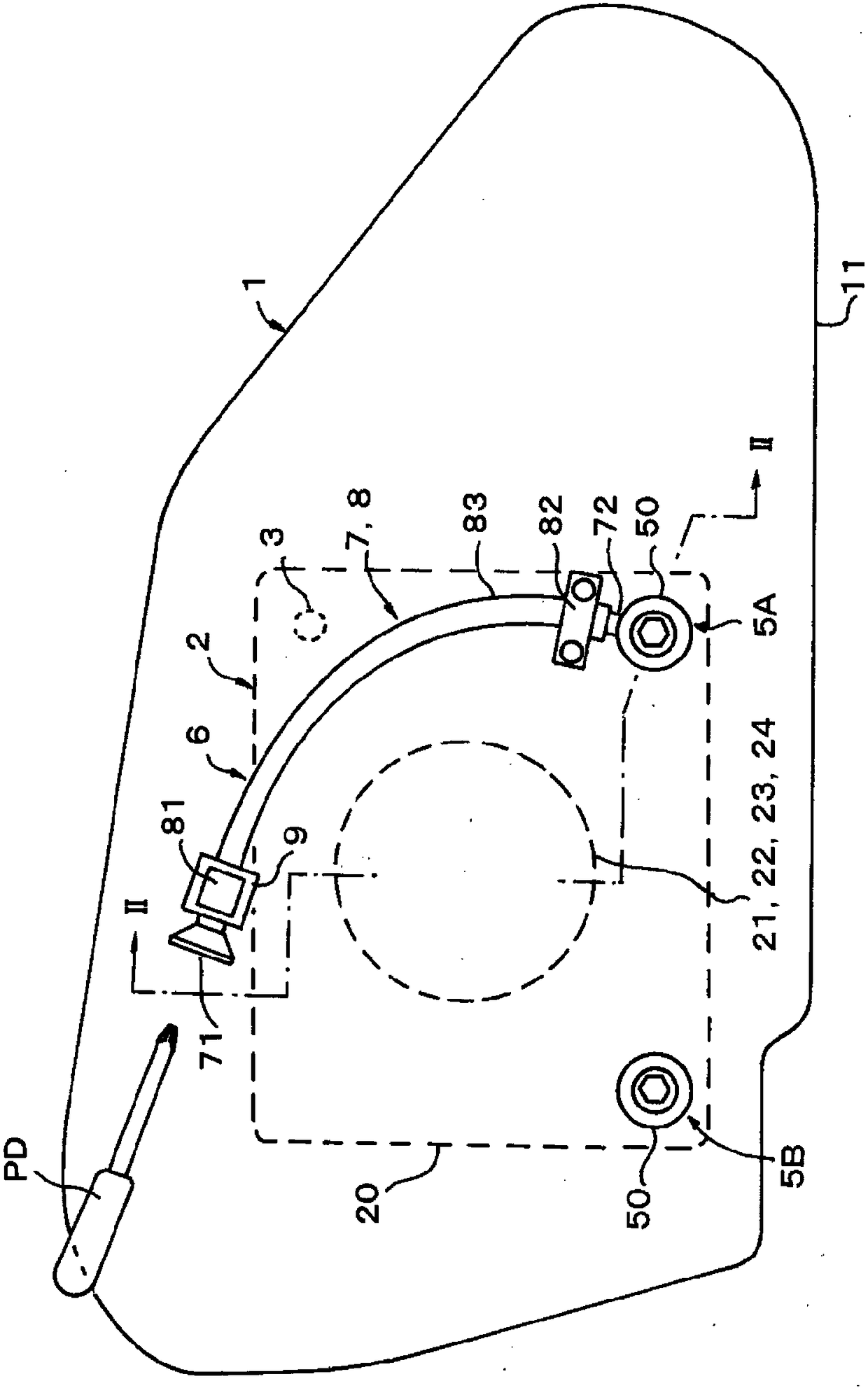
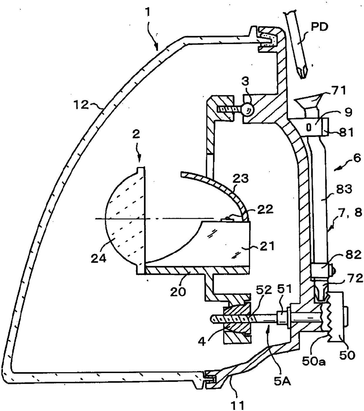
[0054] figure 1 It is the rear view of the left headlight of the automobile to which the present invention is applied, figure 2 is along figure 1 The enlarged cross-sectional view of the II-II line. Such as figure 2 As shown, the lamp housing 1 is constituted by a resin lamp body 11 and a translucent resin front cover 12 attached to cover the front surface of the lamp body 11 , and the lamp unit 2 is housed in the lamp housing 1 .

[0055] The lamp unit 2 is configured as a projection type lamp unit, and includes a base body 21, a light source 22 such as an LED (light emitting diode) mounted on the base body 21, a reflector 23 fixed to the base body 21 covering the upper area of ​​the light source 22, and The projection lens 24 is fixed to the base 21 at a position in front of the light source 22 . The light emitted from the light source 22 is reflected by the reflector...


PUM


Abstract

The present invention relates to a vehicle lamp. An object of the present invention is to improve the reliability of an operation unit that performs illumination adjustment of a lamp and to improve the operability of the operation unit. The vehicle lamp includes an operation unit (6) for operating a bevel gear (50) for adjusting the optical axis of the lamp (1) in a shaft driving manner. A shaft driving force transmitting body (7) of the operation unit (6) includes an operating lever (71) for shaft driving operation, a driving rod (72) that meshes with the bevel gear (50), and a metal wire (73) that connects the operating lever (71) and the driving rod (72) in the shaft driving direction, and the driving rod (72) is formed of a metal that is difficult to rust. The driving rod is formed bya metal injection molding process. A support member (84) extends between the driving rod (72) and the lamp.

Description

technical field [0001] The present invention relates to a lamp for a vehicle, in particular to a lamp for a vehicle provided with an operating unit for adjusting and operating a beam adjustment (optical axis adjustment) mechanism at other positions. Background technique [0002] Headlights (headlights) of vehicles such as automobiles are provided with a beam adjustment mechanism for adjusting a light axis to a predetermined angular direction in front of the automobile. As the dimmer adjustment mechanism, generally, a structure is adopted to operate a dimmer screw provided in the lamp housing, for example, to screw the dimmer screw into at least a part of the lamp unit built in the lamp housing. By operating the dimmer screw on the outside of the lamp unit to drive its axis, the screwed part of the lamp unit is advanced along the axial direction of the dimmer screw, and the tilt angle of the lamp unit in the up-down direction and left-right direction is adjusted due to the mo...

Claims


Application Information

Patent Timeline
IPC IPC(8): F21S41/141F21V14/02F21V21/14F21W107/10F21Y115/10
CPCF21V14/02F21V21/14
Inventor 立岩丈幸
Owner KOITO MFG CO LTD
Why Eureka
Try Eureka