String-Striking Device of Piano
- Summary
- Abstract
- Description
- Claims
- Application Information
AI Technical Summary
Benefits of technology
Problems solved by technology
Method used
Image
Examples
first embodiment
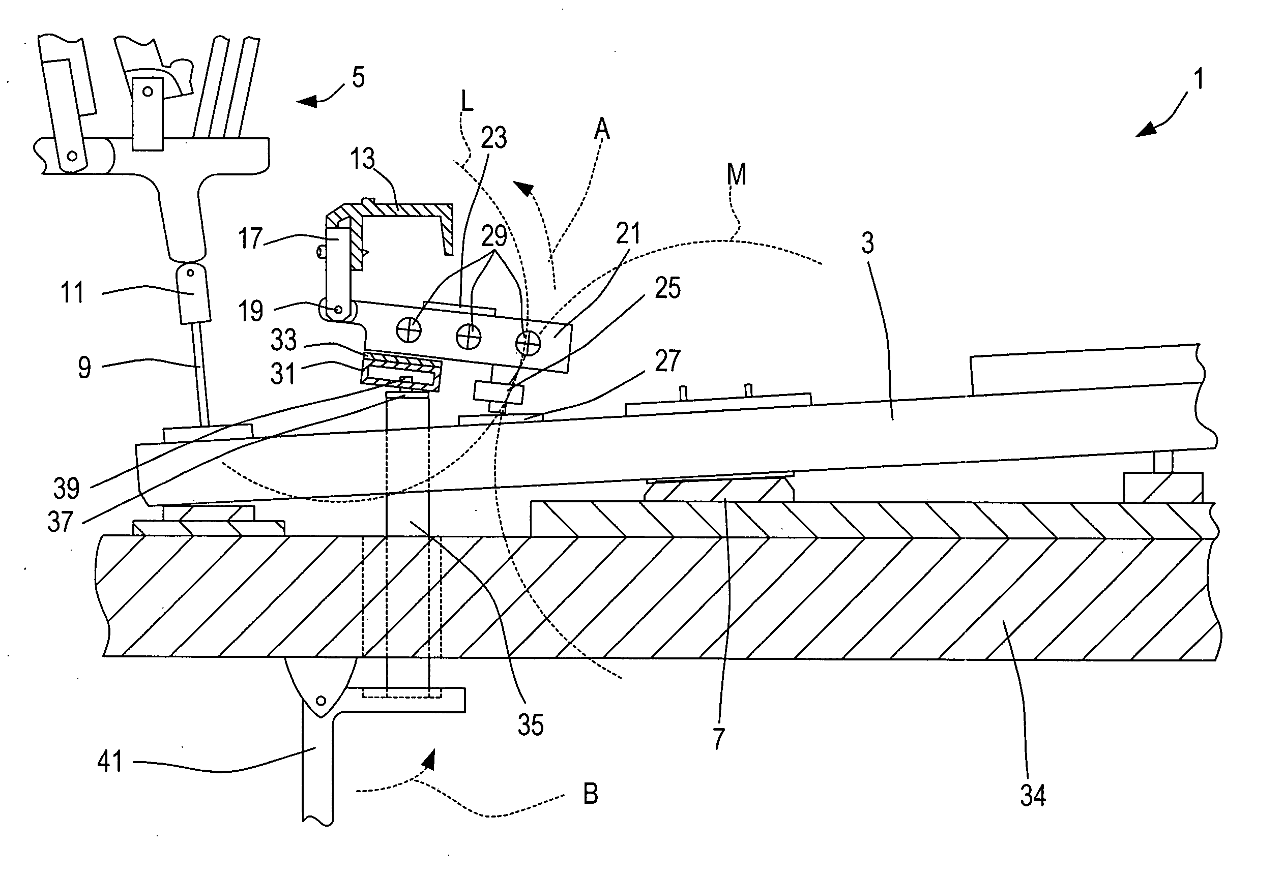
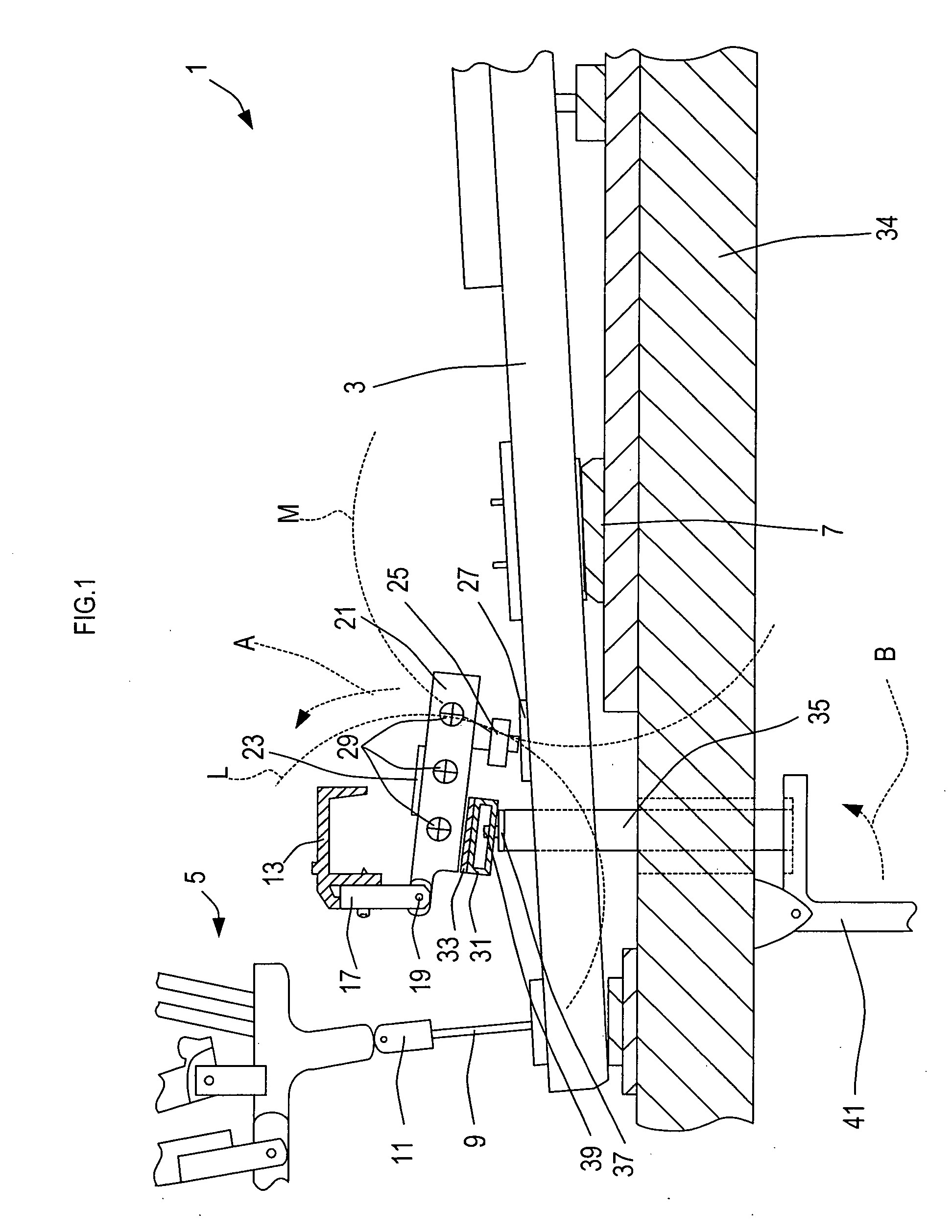
[0029]FIG. 1 is a side view showing a string-striking device 1 of an upright piano. As shown in FIG. 1, the string-striking device 1 mainly comprises a key 3, a transmitting portion 5 (only a part of which is shown), and a hammer portion (not shown). The string-striking device 1 converts the motion of the key 3, resulting from the depression of the key by a player, to the motion of the hammer portion striking a string (not shown).
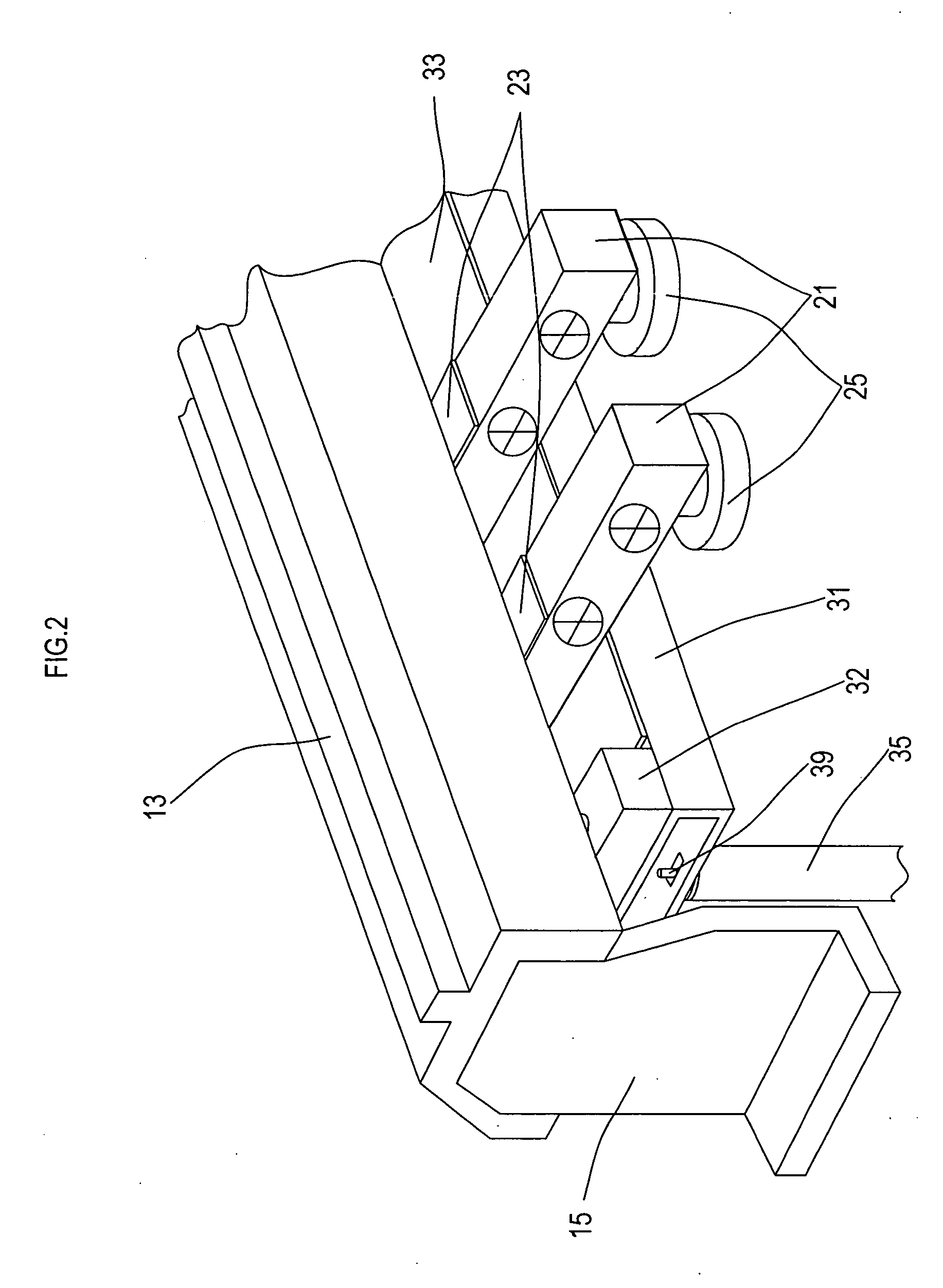
[0030] The piano has a total of 88 individual keys 3. Each key 3 is arranged to pivot on an intermediate plate 7 acting as a fulcrum. When a key 3 is depressed, the side opposite to the player side of the key 3 is raised to transmit the key depression to a transmitting portion 5. Particularly, the key depression is transmitted to the transmitting portion 5, and further to the hammer portion, via a capstan button 11 attached to an end of a capstan wire 9. The capstan wire 9 is provided at an end on the side opposite to the player side of the key 3. Hereinaf...
second embodiment
[0043] From now on, a second embodiment will be described. Hereinafter, mainly only the aspects that are different from the first embodiment are described.
[0044]FIG. 3 is a side view showing a string-striking device 51 of a grand piano. The same reference numbers are given to components identical to those in FIG. 1 and descriptions of those components are not repeated.
[0045] As shown in FIG. 3, the string-striking device 51 mainly comprises a key 3, a transmitting portion 5 (only a part is shown), and a hammer portion (not shown). The string-striking device 51 changes the motion of the key 3 resulting from the key depression by a player to the motion of the hammer portion striking a string (not shown).
[0046] A grand piano has a total of 88 individual keys 3. Each key 3 is arranged to pivot on an intermediate plate 7 acting as a fulcrum. When the front side (right side in FIG. 3) of this key 3 is depressed, the rear side (left side in FIG. 3) of the key 3 is raised so as to transm...
third embodiment
[0055] Next, a third embodiment will be described. Hereinafter, mainly only the aspects that are different than the first embodiment are described.
[0056]FIG. 4 is a side view showing a string-striking device 71 of an upright piano. The same reference numbers are given to the components identical to those in FIG. 1. Therefore, the descriptions of the components are not repeated. As shown in FIG. 4, the weight lever 21 of the string-striking device 71 is different in its setting direction from the weight lever 21 of the string-striking device 1 of the first embodiment (see FIG. 1). The weight lever 21 of the string-striking device 71 is arranged to extend to the rear side (left side of FIG. 4) and swing about a rotation shaft 19. Additionally, the stopper rail 13 and others are disposed in accordance with the arrangement of the weight lever 21. In the first embodiment, the contacting part 25 (see FIG. 1) is provided on the under surface of the weight lever 21 of the string-striking d...
PUM
 Abstract
Description
Claims
Application Information
 - R&D
- Intellectual Property
- Life Sciences
- Materials
- Tech Scout
- Unparalleled Data Quality
- Higher Quality Content
- 60% Fewer Hallucinations
Browse by: Latest US Patents, China's latest patents, Technical Efficacy Thesaurus, Application Domain, Technology Topic, Popular Technical Reports.
© 2025 PatSnap. All rights reserved.Legal|Privacy policy|Modern Slavery Act Transparency Statement|Sitemap|About US| Contact US: help@patsnap.com


