
Method and system for determining radiation shielding thickness and gamma-ray energy

a radiation shielding thickness and gamma-ray energy technology, applied in the field of radiation detection, can solve the problems of affecting the detection effect,

Active Publication Date: 2012-05-10
UCHICAGO ARGONNE LLC
View PDF8 Cites 23 Cited by
  • Summary
  • Abstract
  • Description
  • Claims
  • Application Information

AI Technical Summary

Benefits of technology

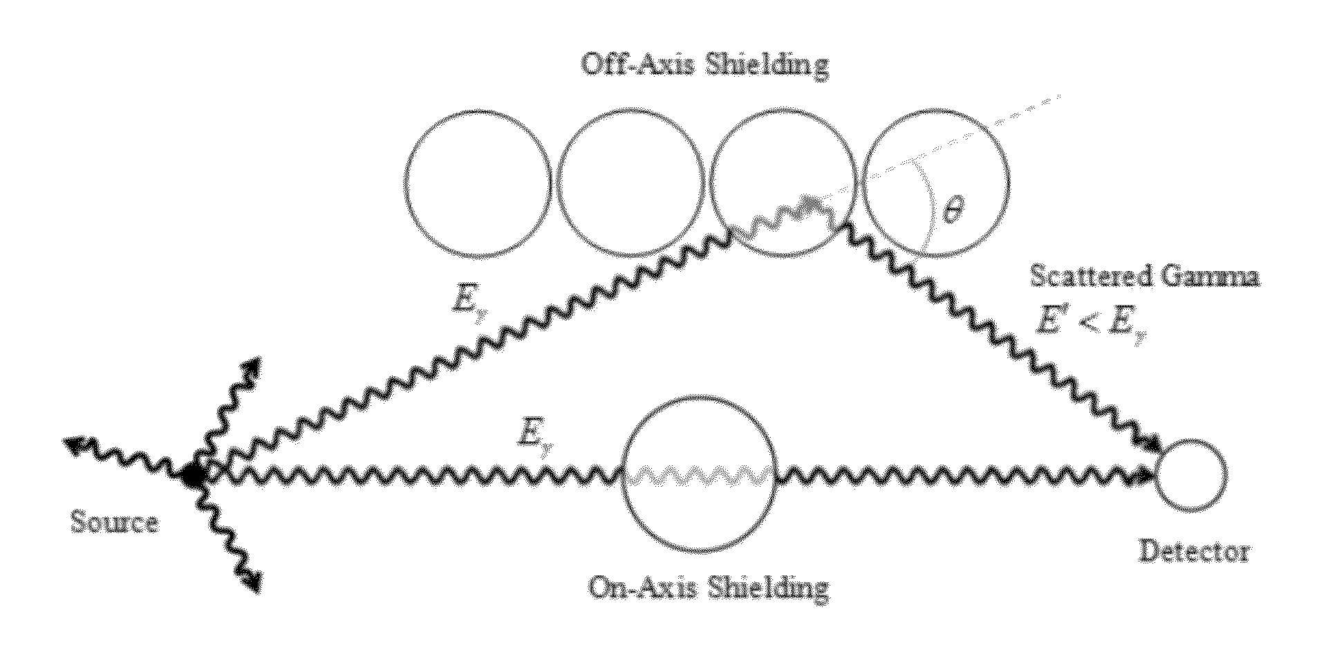
[0008]One embodiment of the invention relates to a method of determining the shielding thickness for a radiation source using a plurality of distributed radiation detectors, a data collection and storage system in communication with the plurality of radiation detectors and a computer system in communication with the data storage and collection system, the computer system comprising a processor and a memory unit. The computer system includes instructions that when executed cause the system to: determine a background count; collect data for a gamma ray spectrum corresponding to each of the plurality of distributed radiation detectors for a predetermined time; normalize the collected gamma ray data; compute the signal as the difference between the background count and the normalized collected gamma ray data; calculate a signal-to-noise ratio using the computed signal; identify a portion of the spectrum corresponding to useful signal based upon the signal-to-noise ratio calculation; normalize the identified portion; compare the normalized identified portion to a predetermined reference; and compute for each of the plurality of distributed radiation detectors a shielding thickness between the radiation source and the respective detector. The system may further include further instructions to compute the location of the radiation source corrected for the computed shielding thickness. The computed location of the radiation source may be expressed in a graphical format, for example, a probability density plot.

Problems solved by technology

After increased publicity of terrorist attacks there has been a fear that terrorists would carry a nuclear weapon or material into the US and cause catastrophic damage.
This is a formidable task given the number of shipping containers, with the added consideration that the nuclear material / device may be in a shielded location.
Some solutions have been developed; however, the detection equipment is not lightweight, nor easily portable, detection times are slow, and require essentially a stationary target.
In a crowded area, spectators provide shielding for the radioactive material in a nuclear device and make source detection difficult.
However, current systems lack the ability of determining the amount of shielding between the radiation source and a radiation detector.

Method used


Image

  • Method and system for determining radiation shielding thickness and gamma-ray energy
  • Method and system for determining radiation shielding thickness and gamma-ray energy
  • Method and system for determining radiation shielding thickness and gamma-ray energy

Examples


Embodiment Construction

[0026]In certain embodiments, the invention relates to a method and a system that utilizes data from an array of gamma-radiation detectors to track the movement of illicit radiological material in real-time while determining and accounting for shielding thickness between the radiation source and detectors. Radiation detectors for use with the present invention have been generally described in related applications; see, for example, U.S. Pat. No. 7,465,924, U.S. patent application Ser. No. 12 / 881,928, and U.S. patent application Ser. No. 12 / 881,943 each of which is incorporated herein by reference.

[0027]One embodiment of the detection system consists of gamma radiation detectors, networking for linking these detectors, signal processing algorithms, and a laptop for running the detection system, including the signal processing algorithms. The system is used to monitor an area and detect the presence of a radioactive source, to localize the position of the source, to track the movement...


PUM


Abstract

A system and method for determining the shielding thickness of a detected radiation source. The gamma ray spectrum of a radiation detector is utilized to estimate the shielding between the detector and the radiation source. The determination of the shielding may be used to adjust the information from known source-localization techniques to provide improved performance and accuracy of locating the source of radiation.

Description

CROSS REFERENCE TO RELATED PATENT APPLICATIONS[0001]The present application claims priority to U.S. Provisional Patent Application No. 61 / 412,267, filed Nov. 10, 2010. The contents of this application are incorporated herein by reference in their entirety.GOVERNMENT INTEREST[0002]The United States Government has rights in this invention pursuant to Contract No. DE-AC02-06CH11357 between the United States Government and the UChicago Argonne, LLC, representing Argonne National Laboratory.FIELD OF THE INVENTION[0003]This invention pertains to radiation detection. More specifically this invention relates to determination of shielding thickness between a gamma-ray source and a detector.BACKGROUND OF THE INVENTION[0004]This section is intended to provide a background or context to the invention that is, inter alia, recited in the claims. The description herein may include concepts that could be pursued, but are not necessarily ones that have been previously conceived or pursued. Therefore...

Claims


Application Information

Patent Timeline
Patent Type & Authority Applications(United States)
IPC IPC(8): G01B11/06
CPCG01B15/02
Inventor KLANN, RAYMOND T.VILIM, RICHARD B.DE LA BARRERA, SERGIO
Owner UCHICAGO ARGONNE LLC
Learn More