Device for controlling gas supply to a burner

Active Publication Date: 2012-05-10
ELTEK
View PDF6 Cites 17 Cited by
  • Summary
  • Abstract
  • Description
  • Claims
  • Application Information

AI Technical Summary

Benefits of technology

[0006]An aim of the present invention is substantially that of overcoming the abovementioned drawbacks and providing a control device—of the type wherein the tap control means or a gas valve and the means for controlling the device itself are substantially mounted coaxial with respect to each other—having a simple structure, having limited overall dimensions, being easy to mount and being versatile in application.

Problems solved by technology

At the end of the set interval, the control unit causes the closure of a safety valve associated to the burner, and thus causing the burner itself going OFF.
The control unit is thus a separate unit with respect to the gas taps that control the burners, and requires considerable housing space within the structure of the apparatus.
Also due to the limited space available inside the apparatus, the installation of the control unit is relatively complex, and requires a particular configuration of the control panel of the apparatus.
Thus, the user is required to operate on several spatially distinct control means, and this may lead to possible setting errors (for example by setting an ignition time for a given burner and then inadvertently igniting a different burner).
On the other hand, in such solutions, the timing function control knob is relatively cumbersome, specifically due to the fact that it houses a timing mechanism.

Method used


Image

  • Device for controlling gas supply to a burner
  • Device for controlling gas supply to a burner
  • Device for controlling gas supply to a burner

Examples


second embodiment

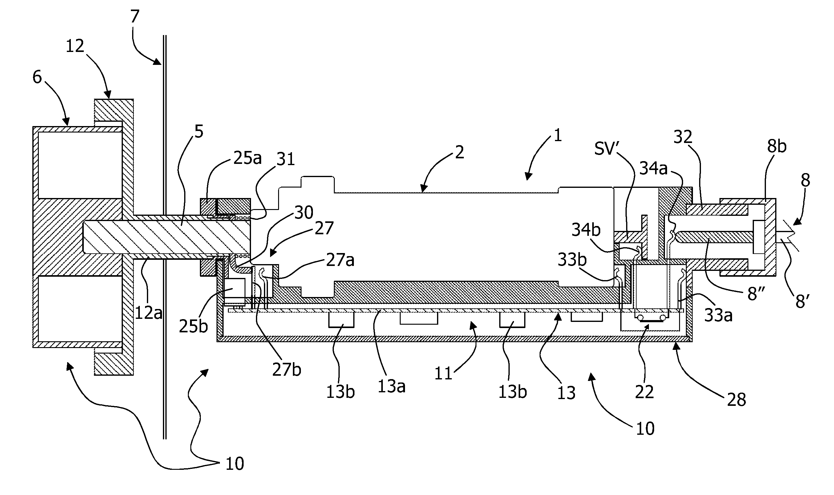
[0068]Illustrated in FIGS. 6-10 is the invention. In such figures the same reference numbers of the previous figures are used to indicate elements technically equivalent to those already described previously.

[0069]In this embodiment the knob 12 is not suitable to slide axially, but is free to rotate, and associated to the manoeuvring shaft 5 of the tap 1—represented solely partly and with configuration of the body 2 different with respect to the first embodiment—is an actuation element 30′, which essentially serves the functions of the element 30 of the first embodiment. The element 30′ is coupled to the shaft 5 in such a manner to allow the free rotation of the latter, and so that pressing the knob 6 causes an axial displacement of the element itself, with the ensuing closure of a contact or control element, indicated with 27′ solely in FIG. 10, substantially serving the functions of the command or switch element 27 of the first embodiment.

[0070]In this case, the functional unit 10...

first embodiment

[0073]The functional unit 10a is herein mounted axially on the tap body 2, mainly inside the structure 7, and is configured to be coupled to such body 2; in the example, the unit has a through opening, coaxial to the tubular body 25a′, into which the proximal end of the tap body 2 is fitted. The shape of the abovementioned through opening may be configured to allow planting—with interference—the body 28 of the unit onto the tap body 2, or provided for may be means for mutual coupling, for example in form of snap-hooks and / or elastic hooks. As in the case of the first embodiment, at least part of the body 28 of the unit 10a of FIGS. 6-9 may be over-moulded onto the tap body 2.

[0074]In this embodiment, the body 28 of the unit 10a is configured in such a manner to have a portion 28d that obtains a sort of electric connector, i.e. it includes a series of electric connections outwards, obtained for example through plate contacts, or of the faston or pin type, as schematically represented...


PUM


Abstract

A gas supply control device for an apparatus, particularly a coking apparatus, includes timing means (20) and a first command means (12) for manually setting a an opening time interval of a safety valve of a gas tap (1), equipped with a second command means (6). In an installed condition of the control device (10), the command means (6, 12) are operable from outside the structure (7) of the apparatus, with the first command means (12) and the second command means (6) substantially rotating around one same axis, one independent from the other. The timing means (20) of the control device (10) belong to a functional unit (10a) which is coupled or configured for coupling with a portion of the body of the tap (2) which portion, in the above mentioned installed conditions, is located inside the structure (7) of the apparatus. The functional unit (10a) includes switch means controllable by timing means for cutting off the electric current to a solenoid of the tap (1) at the end of a time interval set through the first command means (6), and hence causing the passage of the valve to the respective closed condition.

Description

FIELD OF THE INVENTION [0001]The present invention refers to a device for controlling gas supply, for an apparatus having a bearing structure and one or more gas burners, or similar flame generators supplied with gas. More particularly, the invention regards such control device equipped with a timing function, aimed at allowing presetting a desired gas supply time interval of a respective burner.PRIOR ART [0002]Control devices provided with a timing function for gas burners are known.[0003]In some solutions, the device consists of an electric or electronic control unit, configured for controlling all burners of the apparatus (see for example EP-A-1.887.284). This control unit is provided with its own control means capable of allowing setting the time interval for which a given burner shall be kept ON. At the end of the set interval, the control unit causes the closure of a safety valve associated to the burner, and thus causing the burner itself going OFF. The control unit is thus a...

Claims


Application Information

Patent Timeline
IPC IPC(8): F23N5/20F16K31/44F24C3/12
CPCF23K5/007F23K2401/201F23K2900/05001F23N1/00F23N1/007F23N5/107F23N5/20F23N5/203F23N2035/12F23N2035/18F23N2035/22F23N5/12F24C3/126F23N2235/12F23N2235/18F23N2235/22F23K2400/201Y10T137/86397
Inventor GADINI, COSTANZOCOLOMBO, PAOLO
Owner ELTEK
Why Eureka
Try Eureka