
Electronic Transformer Compatibility for Light Emitting Diode Systems

Active Publication Date: 2012-05-10
MAXIM INTEGRATED PROD INC
View PDF6 Cites 33 Cited by
  • Summary
  • Abstract
  • Description
  • Claims
  • Application Information

AI Technical Summary

Benefits of technology

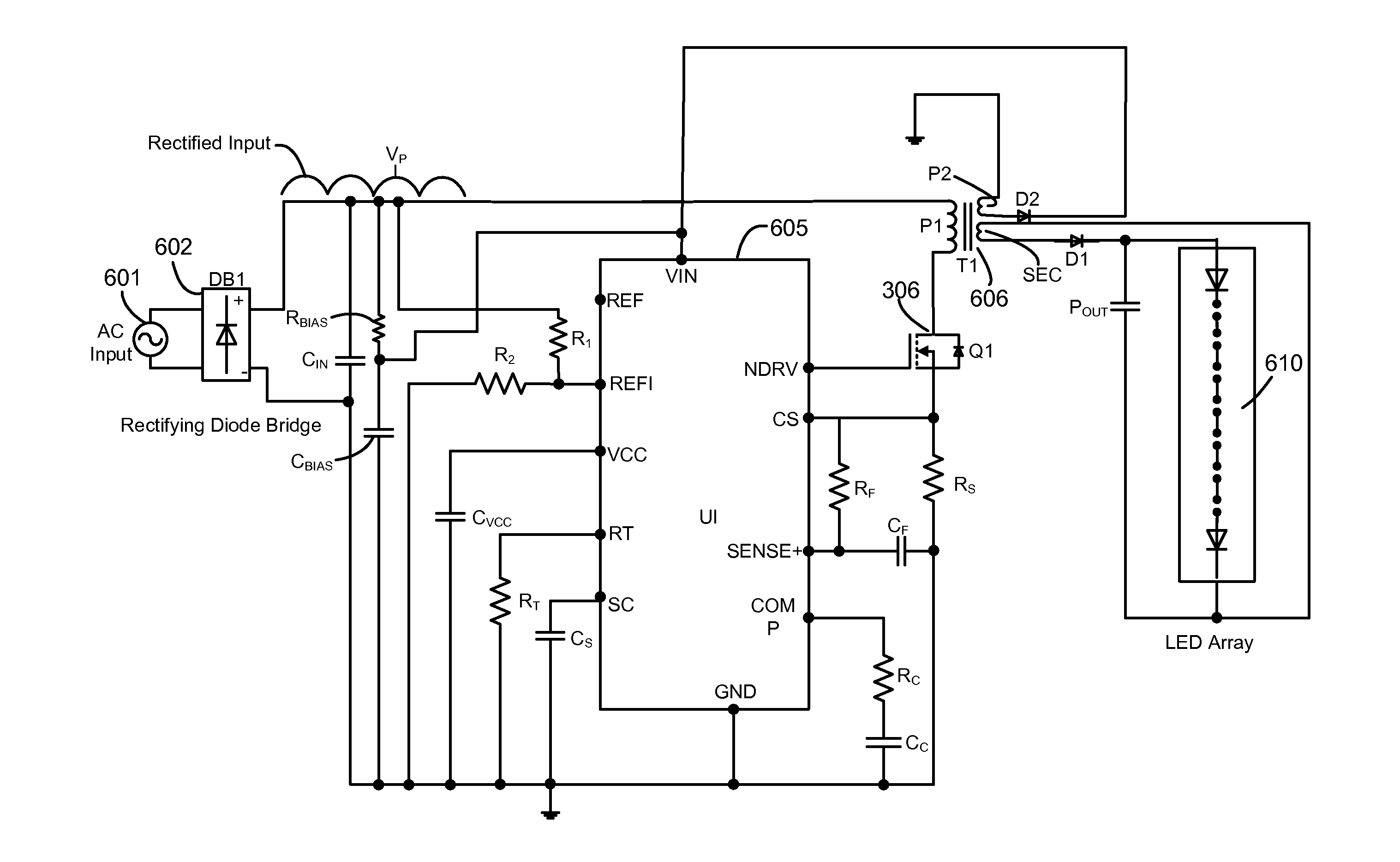
[0015]In some embodiments, the LED driver is an MR16 LED driver and incorporates a current waveform shaper at the positive or negative input of driver. In particular, the current waveform shaper is positioned between an electronic transformer and a bridge rectifier within the driver. The current waveform shaper effectively pulls an increased peak current every switching cycle of the transformer by modifying the waveform of the current received from the transformer. In certain embodiments, the current waveform shaper is an inductor that modifies a square wave current to a triangle wave current being drawn from the rectifier resulting in a relatively higher peak current.

Problems solved by technology

When compared to halogen lamps, LEDs are relatively smaller, and have a longer operating life.
These disadvantages include the use of higher number of total components to drive the LED driver, and a corresponding increase in cost of the LED driver circuitry.
This approach also includes operational inefficiencies, as it requires the input AC source to be converted to DC before applications to the array of LEDs.
Prior art approaches also require the LED current to be measured and monitored in order to achieve PFC, further contributing to the operational inefficiency.
However, the amount of power drawn by an LED is significantly less than the amount drawn by a halogen lamp.
As a result, the compatibility of MR16 LEDs to pre-existing electronic transformers is a significant design issue.

Method used


Image

  • Electronic Transformer Compatibility for Light Emitting Diode Systems
  • Electronic Transformer Compatibility for Light Emitting Diode Systems
  • Electronic Transformer Compatibility for Light Emitting Diode Systems

Examples


Embodiment Construction

[0027]In the following description, for the purpose of explanation, specific details are set forth in order to provide an understanding of the invention. It will be apparent, however, to one skilled in the art that the invention may be practiced without selected of these details. One skilled in the art will recognize that embodiments of the present invention, some of which are described below, may advantageously be incorporated into a number of different devices and systems. Structures and devices shown in block diagram are illustrative of exemplary embodiments of the invention and are included to avoid obscuring the invention. Furthermore, connections between components within the figures are not intended to be limited to direct connections. Rather, such connections between components may be modified, reconfigured, or otherwise changed by intermediary components.

[0028]Reference herein to “one embodiment” or “an embodiment” of the invention means that a particular feature, structure...


PUM


Abstract

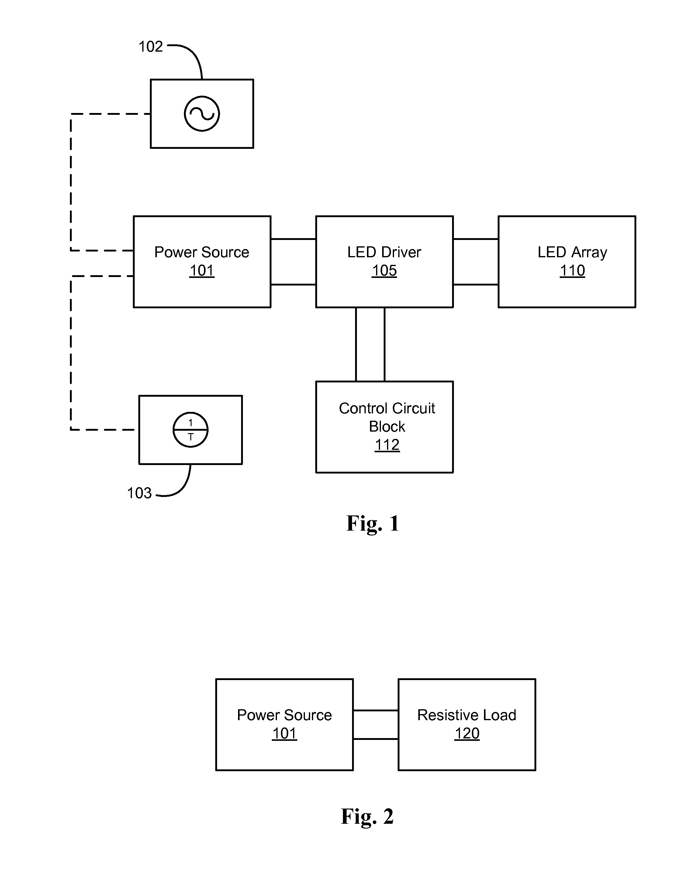
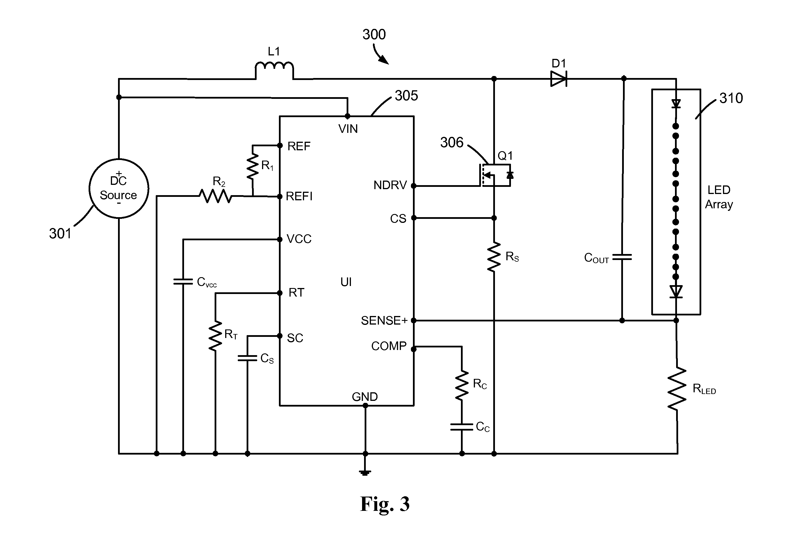
Various embodiments of the invention provide power factor correction in solid state lighting applications. In certain embodiments, an LED driver for an LED array is controlled for power factor correction by a control circuit block. The control circuit block comprises electronic circuitry that enables the input current to the LED driver to be measured and controlled. This control circuit block comprises at least one switching device that enables an alternating form of current at a particular frequency to be applied to the LED array regardless of whether the main power source is a DC or AC power source.

Description

CROSS REFERENCE TO RELATED PATENT APPLICATIONS[0001]This application claims priority to U.S. provisional application Ser. No. 61 / 411,362, entitled “Electronic Transformer Compatibility for Light Emitting Diode Systems,” filed Nov. 8, 2010, which application is incorporated herein by reference in its entirety.BACKGROUND[0002]1. Field of the Invention[0003]The present invention relates to a control system for controlling currents in an electronic system. More particularly, the present invention relates to a control system for controlling the current in drivers for solid-state lighting (SSL) devices, such as, for example, a light emitting diode (LED) or an array or cluster of light emitting diodes (LEDs) having driver circuitry that is compatible with electronic transformers and supports dimming functionality. It also improves the compatibility of LED systems to certain types of electronic transformers by enhancing current flow through the transformer.[0004]2. Background of the Inventi...

Claims


Application Information

Patent Timeline
IPC IPC(8): H05B37/02
CPCY02B70/126H02M1/4208Y02B20/383H05B33/0845H05B33/0815H05B45/10H05B45/382H05B45/38H05B45/355Y02B20/30Y02B70/10H05B45/3725
Inventor HARIHARAN, SURESH
Owner MAXIM INTEGRATED PROD INC
Learn More