Control apparatus for internal combustion engine
- Summary
- Abstract
- Description
- Claims
- Application Information
AI Technical Summary
Benefits of technology
Problems solved by technology
Method used
Image
Examples
first embodiment
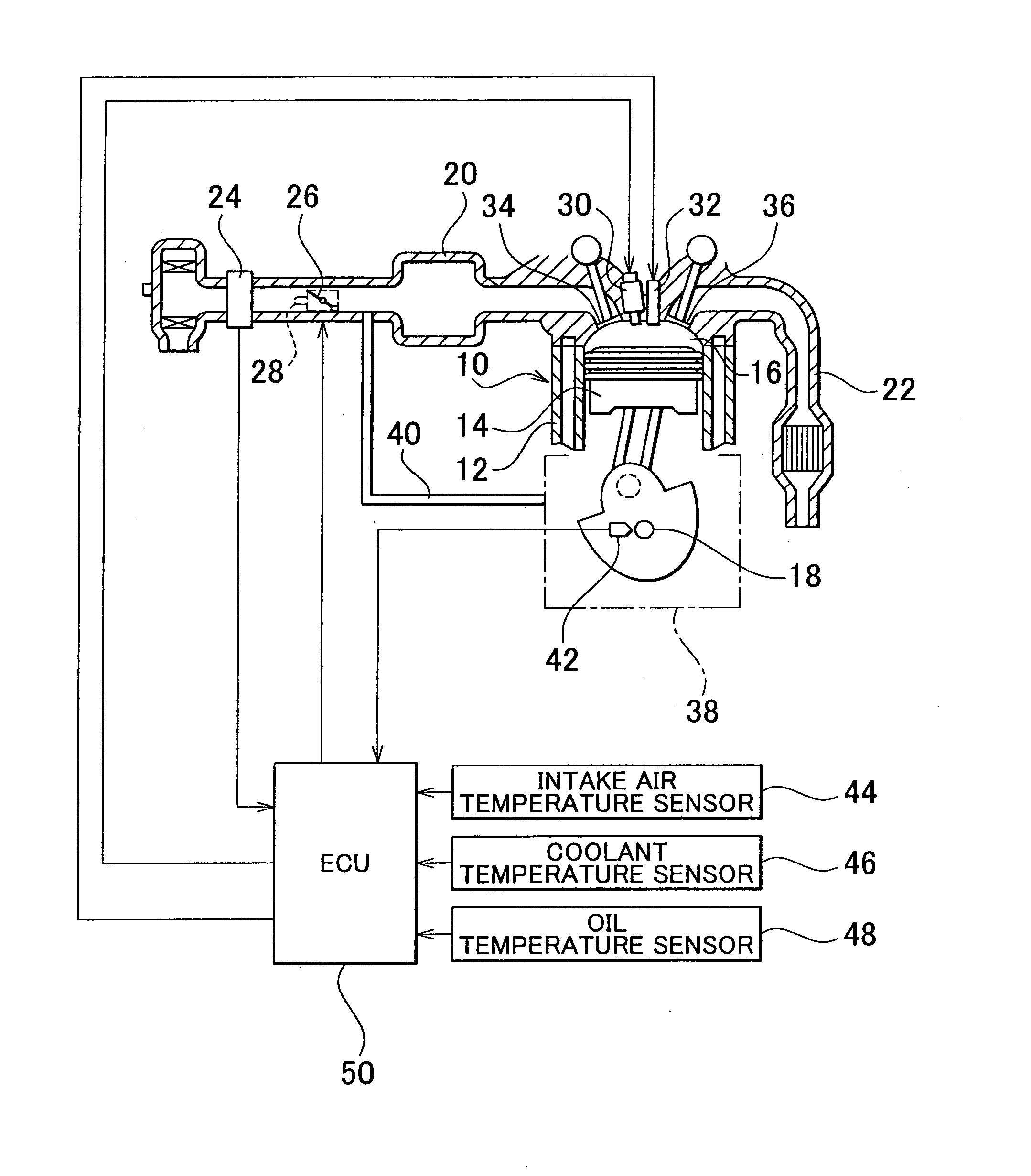
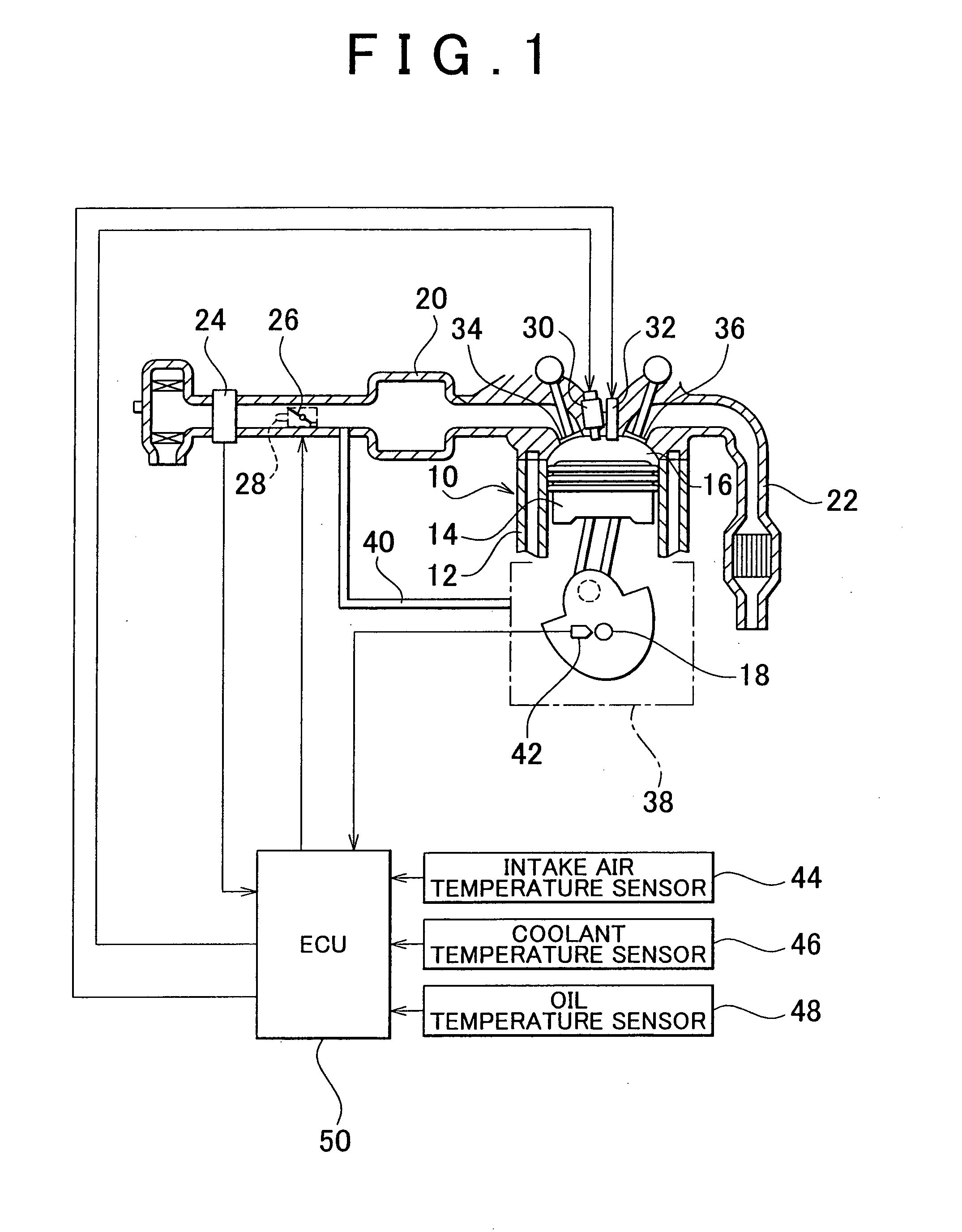
[0045]Furthermore, the system according to the invention is equipped with a sensor group including a crank angle sensor 42, an intake air temperature sensor 44, a coolant temperature sensor 46, an oil temperature sensor 48, and the like, and an electronic control unit (ECU) 50 that controls an operation state of the internal combustion engine 10. The crank angle sensor 42 outputs a signal synchronized with rotation of the crankshaft 18. The ECU 50 detects an engine rotational speed on the basis of an output of the crank angle sensor 42.
[0046]Further, the intake air temperature sensor 44 detects a temperature of intake air (an outside air temperature), and constitutes air temperature detection means. On the other hand, the coolant temperature sensor 46 detects a temperature of coolant for the internal combustion engine (a coolant temperature Tw). The oil temperature sensor 48 detects a temperature of lubricating oil in the oil pan 38 (an oil temperature To). These two sensors, namely...
second embodiment
[0080](Oil Temperature Estimation Control during Restart) As described above, when the predetermined start condition is fulfilled during automatic stop of the internal combustion engine, idle stop control is terminated to restart the internal combustion engine. At this moment, the oil temperature of lubricating oil has fallen correspondingly to the stop time of the engine, and displays a behavior different from a behavior in the case where the operation of the engine is continued. Thus, in this second embodiment of the invention, the oil temperature during the restart of the internal combustion engine is estimated in consideration of the stop time of the internal combustion engine.
[0081]To be more specific, first of all, when the internal combustion engine is stopped through idle stop control, a stop oil temperature Tos as an oil temperature of lubricating oil that is detected or estimated upon the stop of the internal combustion engine is stored into the ECU 50. It should be noted ...
third embodiment
[0091]Changeover control for making a changeover from the aforementioned engine running to the aforementioned motor running constitutes engine stop control according to this third embodiment of the invention, and is performed when a predetermined stop condition determined on the basis of, for example, the operation states of the vehicle and the internal combustion engine, the state of charge of the battery, and the like is fulfilled. An example of this stop condition is that “the required driving force of the vehicle be smaller than an engine stop required reference value engstop (hereinafter referred to as a stop required output engstop)”. It should be noted herein that the stop required output engstop is a lower limit of the engine output at which engine running is more advantageous than motor running. As shown in FIG. 7, the stop required output engstop is expressed as one of iso-output lines obtained by connecting points at which the output of the internal combustion engine is c...
PUM
 Abstract
Description
Claims
Application Information
 - Generate Ideas
- Intellectual Property
- Life Sciences
- Materials
- Tech Scout
- Unparalleled Data Quality
- Higher Quality Content
- 60% Fewer Hallucinations
Browse by: Latest US Patents, China's latest patents, Technical Efficacy Thesaurus, Application Domain, Technology Topic, Popular Technical Reports.
© 2025 PatSnap. All rights reserved.Legal|Privacy policy|Modern Slavery Act Transparency Statement|Sitemap|About US| Contact US: help@patsnap.com


