
Cryogenic-radiofrequency ablation system

a radiofrequency ablation and cryogenic technology, applied in the field of medical devices, can solve the problems of exposing patients to undesired risks, limited operation range, and long time-consuming, and achieve the effect of increasing the size of frozen portions

Inactive Publication Date: 2012-05-03
MEDTRONIC ABLATION FRONTIERS
View PDF8 Cites 29 Cited by
  • Summary
  • Abstract
  • Description
  • Claims
  • Application Information

AI Technical Summary

Benefits of technology

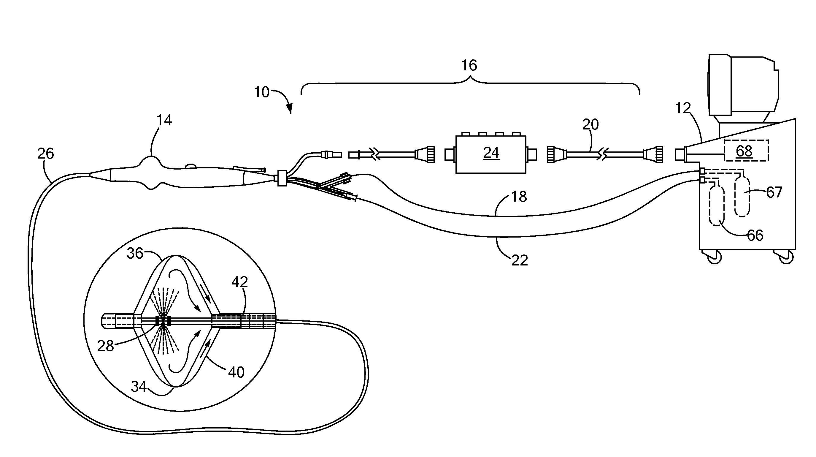
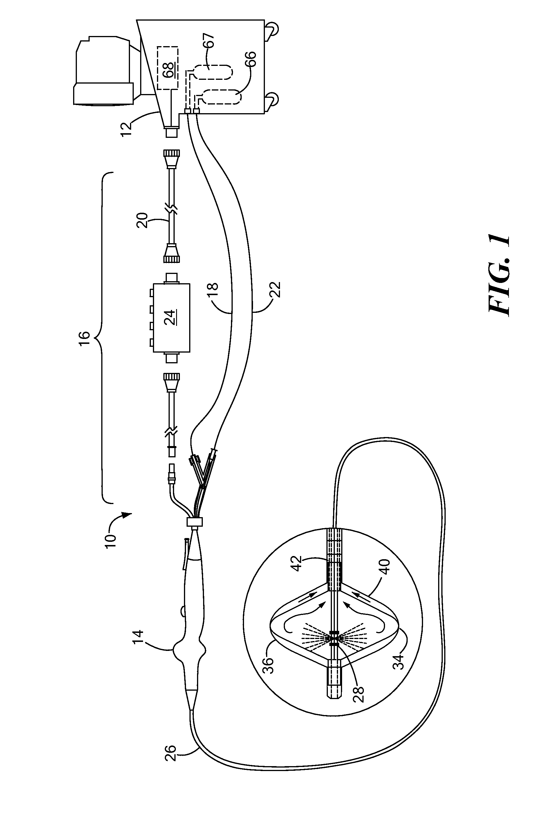
[0011]A method of treating a cardiac tissue site proximate an orifice, such as a pulmonary vein opening, is disclosed as including substantially occluding the orifice with an expandable element; powering a plurality of electrodes coupled to the expandable element to reach a predetermined target temperature; circulating a coolant through the expandable element to freeze portions of the cardiac tissue site located between the plurality of electrodes; and ablating the non-frozen portions of the tissue site with the plurality of electrodes. The method may include modulating the circulation of coolant to increase the size of the frozen portions of the cardiac tissue site and / or modulating the powering of the plurality of electrodes to substantially maintain the predetermined target temperature.

Problems solved by technology

Such limited range of operation may necessitate lengthy treatment procedures involving many iterations of ablative lesion forming, and re-mapping or checking the quality of lesion or symptomatic presence prior to completing a treatment procedure.
Such steps may require a lengthy amount of time to perform, thus exposing the patient to undesired risk.
Cryogenic lesion creation having sufficient depth may take longer to generate compared to RF treatment, and may require similar repetitions of e-mapping or checking the quality of lesion or symptomatic presence prior to completing a treatment procedure

Method used


Image

  • Cryogenic-radiofrequency ablation system
  • Cryogenic-radiofrequency ablation system
  • Cryogenic-radiofrequency ablation system

Examples


Embodiment Construction

[0018]The present invention advantageously provides a medical system and methods of use thereof to achieve an extended range of thermal transfer while ablating tissue more effectively and to a greater depth. Referring now to the drawing figures in which like reference designations refer to like elements, an embodiment of a medical system constructed in accordance with principles of the present invention is shown in FIG. 1 and generally designated as “10.” Of note, the device components have been represented where appropriate by conventional symbols in the drawings, showing only those specific details that are pertinent to understanding the embodiments of the present invention so as not to obscure the disclosure with details that will be readily apparent to those of ordinary skill in the art having the benefit of the description herein. Moreover, while certain embodiments or figures described herein may illustrate features not expressly indicated on other figures or embodiments, it i...


PUM


Abstract

A medical treatment system, including a catheter body defining a fluid flow path therethrough; an expandable element disposed on the catheter body, the expandable element defining a cooling chamber therein in fluid communication with the fluid flow path; a plurality of electrodes disposed on the expandable element; a cryogenic fluid source in fluid communication with the fluid flow path; and a radiofrequency energy source in electrical communication with the plurality of electrodes. A method of treating a cardiac tissue site proximate an orifice, including substantially occluding the orifice with an expandable element; powering a plurality of electrodes coupled to the expandable element to reach a predetermined target temperature; circulating a coolant through the expandable element to freeze portions of the cardiac tissue site located between the plurality of electrodes; and ablating the non-frozen portions of the tissue site with the plurality of electrodes.

Description

CROSS-REFERENCE TO RELATED APPLICATION[0001]n / aSTATEMENT REGARDING FEDERALLY SPONSORED RESEARCH OR DEVELOPMENT[0002]n / aFIELD OF THE INVENTION[0003]The present invention relates to medical devices and methods of use thereof, and in particular towards medical devices for the thermal treatment of tissue.BACKGROUND OF THE INVENTION[0004]Minimally invasive devices, such as catheters, are often employed for medical procedures, including those involving ablation, dilation, and the like. In a particular situation, an ablation procedure may involve creating a series of inter-connecting or otherwise continuous lesions in order to electrically isolate tissue believed to be the source of an arrhythmia. Such lesions may be created using a variety of different energy transmission modalities, such as cryogenic freezing or heating with radiofrequency (“RF”) energy[0005]Catheters or devices using cryogenic cooling may be used to lower the temperature of tissue, such as cardiac wall tissue, to an ext...

Claims


Application Information

Patent Timeline
IPC IPC(8): A61B18/02A61B18/18
CPCA61B2018/00791A61B2018/00875A61B2018/00994A61B2018/0212A61B2018/0262A61N1/403A61B18/02A61B18/1492A61B2018/0016A61B2018/00255A61B2018/00375A61B2018/00642A61B2018/00678A61B2018/00702A61B2018/00714A61B2018/00744
Inventor LALONDE, JEAN-PIERRECONDIE, CATHERINE R.
Owner MEDTRONIC ABLATION FRONTIERS
Learn More