
Reactor

Active Publication Date: 2012-05-03
KOBE STEEL LTD
View PDF3 Cites 14 Cited by
  • Summary
  • Abstract
  • Description
  • Claims
  • Application Information

AI Technical Summary

Benefits of technology

[0022]According to the present invention, it is possible to realize a reactor in which high inductance generates stably over a wide current range, while suppressing noise, manufacturing cost and eddy current loss.

Problems solved by technology

However, in a case of such a gap being provided in a core member, problems in noise and magnetic flux leakage generally arise.
In addition, the dimensional precision of the gap provided to the core member influences the inductance characteristic of the reactor; therefore, disadvantages also arise in that it is necessary to precisely form the gap, and manufacturing cost of the reactor increases.
Employing a ceramic material may be included in the gap portion as noise control; however, there is a problem in that the manufacturing cost of the reactor increases also due to such noise control.

Method used


Image

  • Reactor
  • Reactor
  • Reactor

Examples


Embodiment Construction

[0075]Hereinafter, embodiments according to the present invention will be explained based on the drawings. It should be noted that the configurations to which the same symbol is assigned in each of the drawings indicate the same configuration, and explanations thereof will be omitted as appropriate.

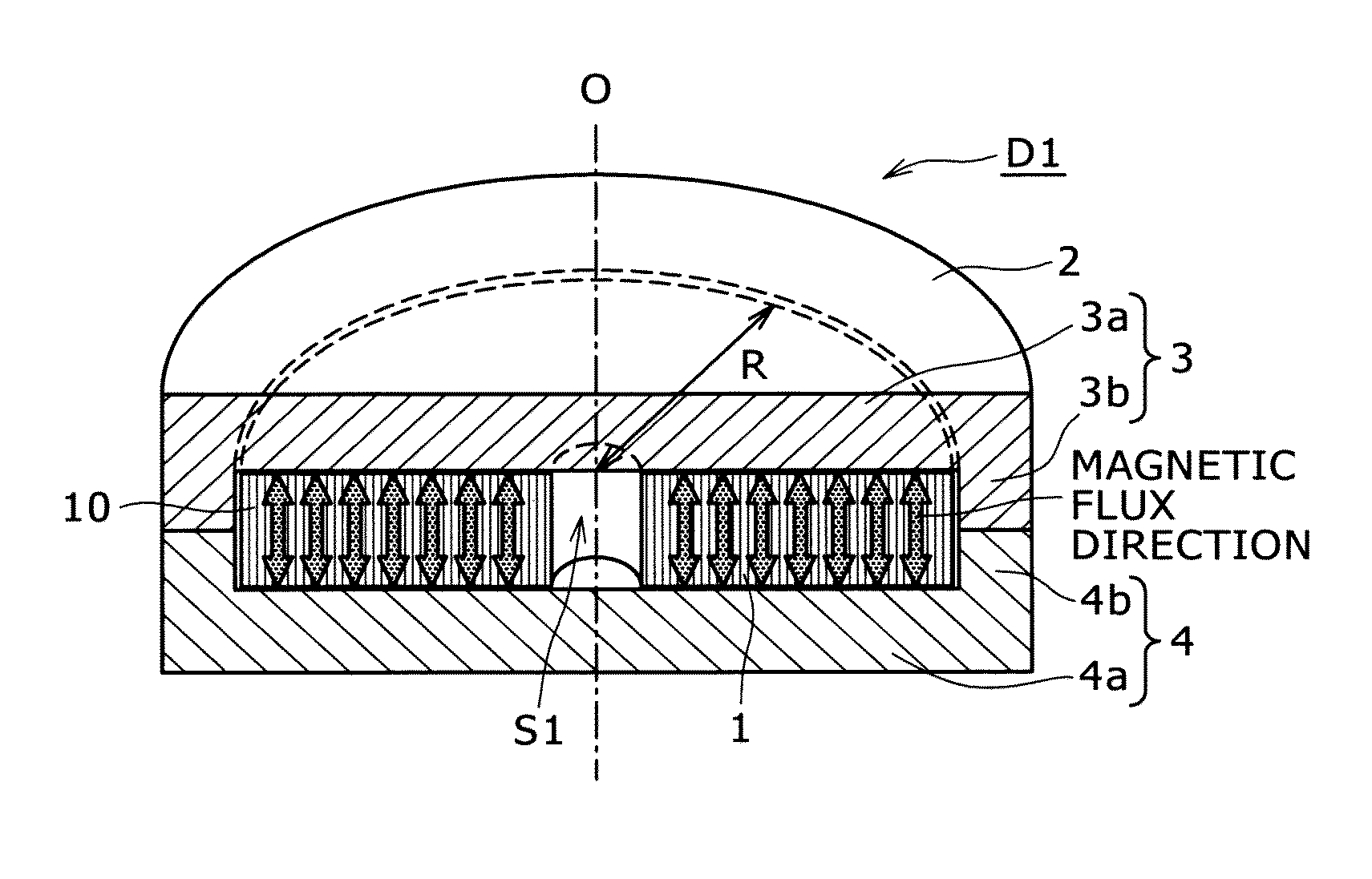
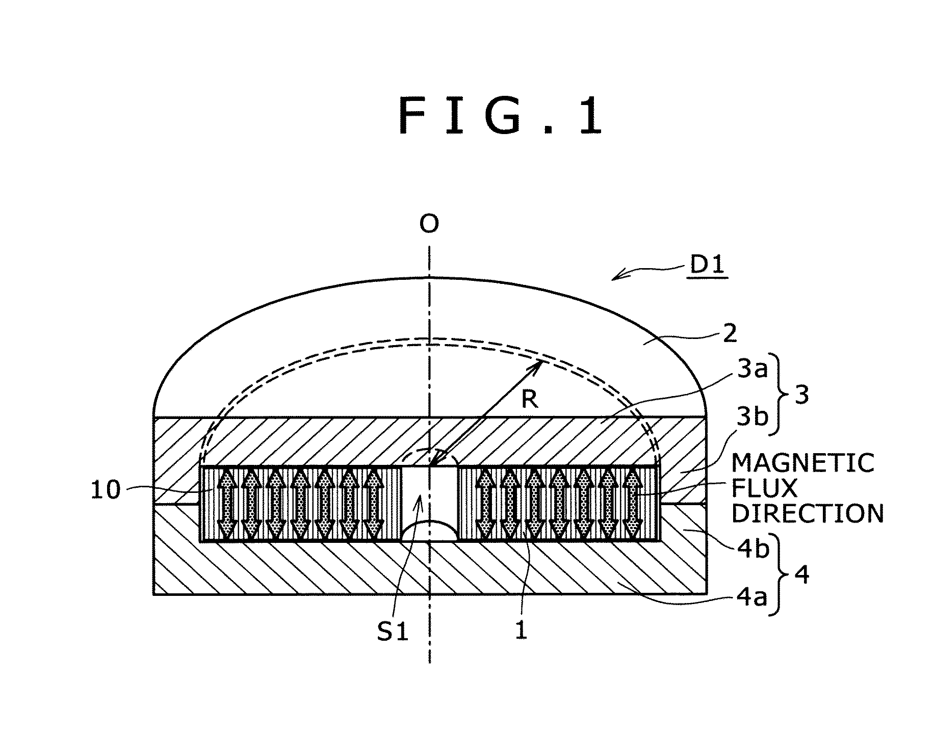
[0076]Hereinafter, an embodiment of a reactor according to the present invention will be explained. FIG. 1 shows a first embodiment of a reactor according to the present invention, and is a cross-sectional view sectioned in a plane including an axis-center O. FIG. 2 is a perspective view showing another form of a core member in the reactor of the first embodiment.

[0077]As shown in FIG. 1, a reactor D1 includes an air-core coil 1 having a flat-wise winding structure described later, and a core portion 2 that covers the air-core coil 1. It should be noted that an explanation will be made from the core portion 2 for convenience of explanation.

[0078]The core portion 2 includes first and secon...


PUM


Abstract

Provided is a reactor that enables high inductance to be generated with stability in a wide current range, while minimizing noise, processing cost, and eddy-current loss. The reactor (D1) has the ratio (t / W) of the width (W) to the thickness (t) of a conductive member that composes an air-core coil configured to be 1 or less, and preferably, 1 / 10 or less. Furthermore, the reactor also has the absolute value of a value ((L1−L2) / L3) that has had: the difference (L1−L2) between; the space interval (L1) between an inner wall face of a first core member (3) and an inner wall face of a second core member (4), at the innermost circumference position of the air-core coil (1); and the space (L2) between the inner wall face of the first core member (3) and the inner wall face of the second core member (4), at the outermost circumference position of the air-core coil (1); divided by an average value (L3); configured to be 1 / 50 or less. The ratio (R / W) of the radius (R), from the axis-center (O) of the air-core coil (1) to the outer circumference of the air-core coil (1), to the width (W) of the air-core coil (1) (conductive member), is 2=R / W=4.

Description

TECHNICAL FIELD [0001]The present invention relates to a reactor that is suitably utilized in electrical circuits, electronic circuits, and the like, for example.BACKGROUND ART [0002]Reactors that are passive elements employing windings are used in various electric circuits and electronic circuits such as for the prevention of harmonic current in a power factor improvement circuit, the smoothing of current pulsation in a current source inverter and chopper control, and the step-up of direct current voltage in a converter. There are Patent Literature 1 to Patent Literature 4 as technical literature related to this type of reactor, for example.[0003]Patent Literature 1 discloses a reactor including a coil, a core composed of a magnetic powder mixed resin that is packed inside and at the outer circumference of the coil, and a case that accommodates the coil and core, further including protrusions formed on an inner wall face of the case.[0004]Patent Literature 2 discloses a reactor inc...

Claims


Application Information

Patent Timeline
IPC IPC(8): H01F27/00
CPCH01F3/14H01F27/2847H01F37/00H01F27/24H01F27/28
Inventor MITANI, HIROYUKIZAITSU, KYOJIINOUE, KENICHIOZAKI, OSAMUHASHIMOTO, HIROSHIHOJO, HIROFUMIINOUE, KOJIYOSHIKAWA, EIICHIROFUJIWARA, NAOYA
Owner KOBE STEEL LTD
Learn More