Miniature automatic shutoff nozzle tip

a technology of automatic shutoff and nozzle tip, which is applied in the field of plastic extruders, can solve the problems of affecting the quality of parts deeming them defective, no compelling reason for fluid, and a higher pressure drop than the standard nozzle tip, so as to prevent drooling or stringing, reduce melt pressure, and prolong the length

Active Publication Date: 2012-04-26
DURINA MICHAEL F
View PDF3 Cites 3 Cited by
  • Summary
  • Abstract
  • Description
  • Claims
  • Application Information

AI Technical Summary

Benefits of technology

[0004]Standard nozzle tips such as U.S. Pat. No. 6,604,933 rely on the plastic fluid to “freeze-off” at the distal end of the orifice so as to prevent drooling or stringing to occur when the mold is opened. Drooling and stringing occur because of the differential between the internal pressures of the molten plastic fluid which can be as high as 5000 psi and atmospheric pressure. If freeze-off does not occur then the molten fluid will transfer into the sprue bushing of the mold and deter the flow of the incoming fluid during the injection forward portion of the next cycle. This interference will affect the quality of the parts deeming them defective. Most standard nozzle tips do not “freeze-off” so the industry wide solution is to use a molding method called melt decompression, which reverses the motion of the screw at the end of screw rotate so as to lower the melt pressure making it somewhat equivalent to atmospheric pressure and hence no compelling reason for the fluid to flow into the mold. Another solution is to provide an automatic shutoff nozzle or needle shutoff nozzle which is shown and described in U.S. Pat. No. 7,291,008. Automatic needle shutoff nozzles of this type are more precise functionally in stopping the flow of the polymer but they are typically much longer in length, more complicated and more expensive and have a higher pressure drop than the standard nozzle tip. All Automatic needle shutoff nozzles employ a needle tip / pin that is placed in the center of a nozzle body that shuts off against a seat that is positioned at the distal end of the nozzle body and upstream of the nozzle orifice passageway. The needle that is centered in the melt stream impedes the flow of the molten plastic fluid and complicates the design. In addition, most needle valves are operated by an external force such as a spring or a pneumatic piston that is attached to an armature which extends to the needle pin through a hole in the body. The hole is sealed so as to prevent leakage of the high pressure molten fluid and the seals are subject to failure. The miniature automatic nozzle tip of this invention is an automatic shutoff device that utilizes a spring or the like component to provide the force to urge a poppet towards a seat that is held in the normally closed position and is positioned downstream of the nozzle tip opening, and opened when the force of the plastic fluid exceeds the force of the spring. The nozzle tip of this invention is miniature in size, has no external moving parts, is easily attached and removed to a nozzle body and provides a precise seal who's design is unlike any prior art.

Problems solved by technology

This interference will affect the quality of the parts deeming them defective.
Most standard nozzle tips do not “freeze-off” so the industry wide solution is to use a molding method called melt decompression, which reverses the motion of the screw at the end of screw rotate so as to lower the melt pressure making it somewhat equivalent to atmospheric pressure and hence no compelling reason for the fluid to flow into the mold.
Automatic needle shutoff nozzles of this type are more precise functionally in stopping the flow of the polymer but they are typically much longer in length, more complicated and more expensive and have a higher pressure drop than the standard nozzle tip.
The needle that is centered in the melt stream impedes the flow of the molten plastic fluid and complicates the design.
The hole is sealed so as to prevent leakage of the high pressure molten fluid and the seals are subject to failure.

Method used


Image

  • Miniature automatic shutoff nozzle tip
  • Miniature automatic shutoff nozzle tip
  • Miniature automatic shutoff nozzle tip

Examples


Embodiment Construction

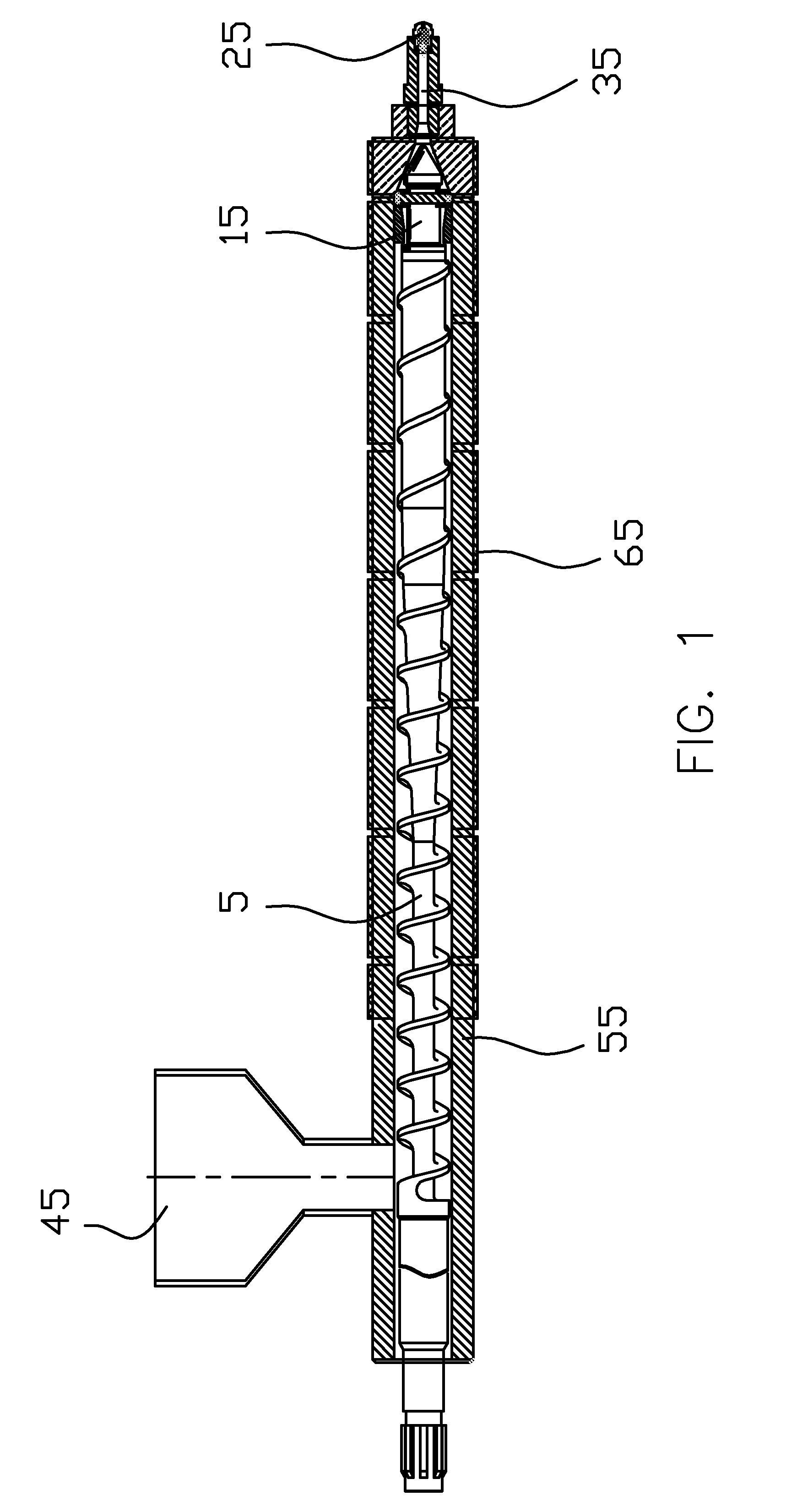
[0010]FIG. 1 represents a cross sectional view of a plasticating unit for an injection molding machine. The plasticating unit includes a heated elongated barrel 55 enclosing a reciprocating and rotating helical screw 5 which is fed plastic pellets through a material hopper 45 filled with solid resinous material particles that are not shown and an inlet port for admission of one or more solid particulate resinous materials and any required additives or agents. The screw 5 comprises a helical flight that wraps around a core that forms a channel for conveyance of the plastic pellets from the inlet section along the axis while the apparatus is heated by heaters so that the pellets become melted during transit within barrel 55. This operation and apparatus is described more fully in U.S. Pat. No. 4,752,136.

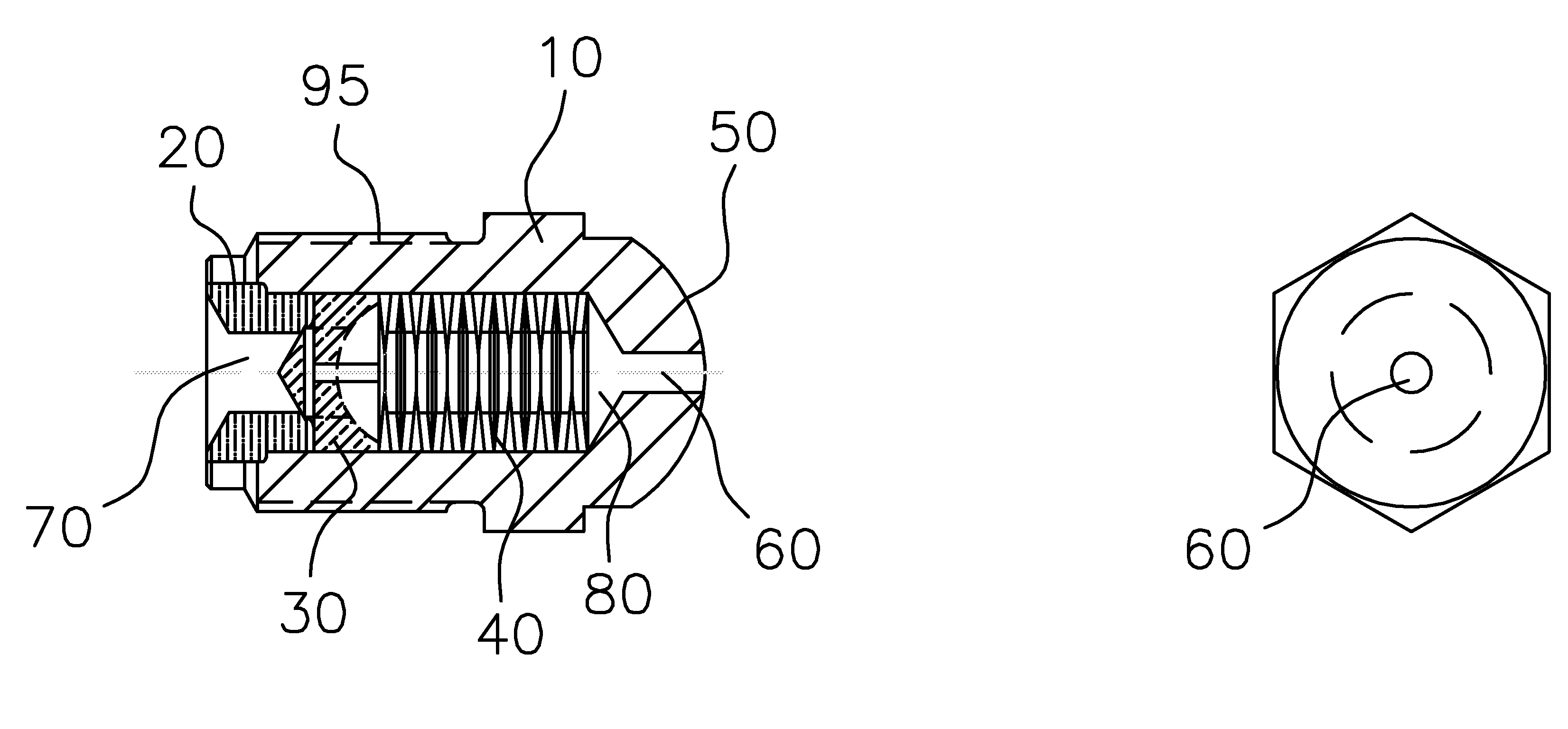
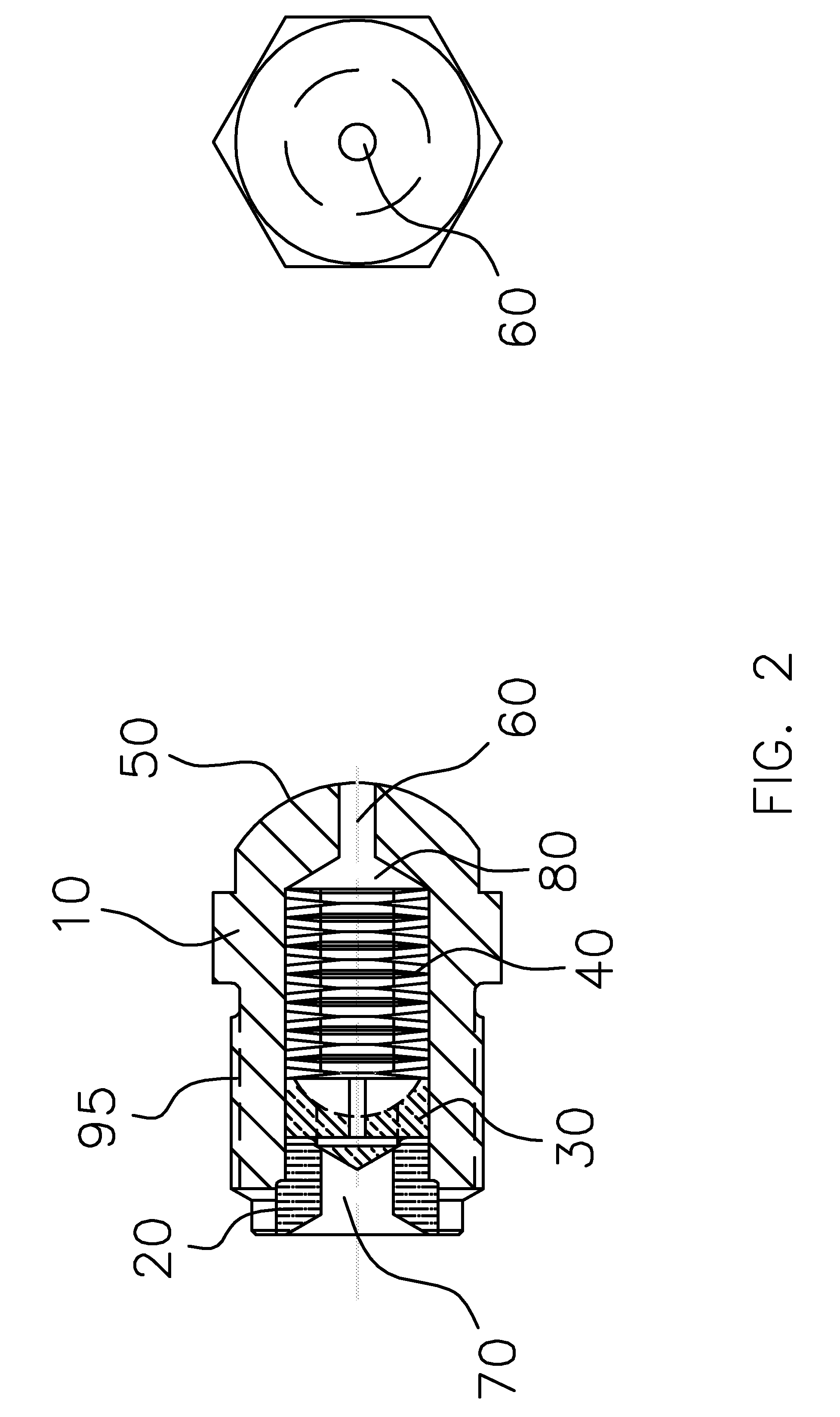
[0011]The non-return valve 15 is located at the forward end of the rotating screw 5. The screw is shown with the non-return valve 15 in the open position which allows molten plastic fl...


PUM

PropertyMeasurementUnit
internal pressuresaaaaaaaaaa
diameteraaaaaaaaaa
sizeaaaaaaaaaa

Abstract

An improved automatic shutoff nozzle tip which is mounted on the downstream end of a nozzle body of an injection molding machine or the like who's purpose is to act as a passageway for molten plastic fluid allowing the fluid to flow in one direction when urged to open by the pressure created by the forward motion of the plasticizing screw of said molding machine and to close when said pressure is lower than the designed opening pressure. The nozzle, having an convex outwardly extended portion that mates up with a sprue bushing or mold having complimentary convex radii, said nozzle having a orifice on the distal end that mates with a complimentary orifice of said sprue bushing. A nozzle that has a means for attachment to a nozzle body or the like with a rear seat, poppet and spring or similar device who's poppet is normally in the closed position until pressure is applied urging the poppet to move in the downstream direction and providing for a passageway for molten plastic fluid.

Description

FIELD OF THE INVENTION[0001]This invention relates to a reciprocating plastic extruder and more particularly this invention relates to a miniature automatic shutoff nozzle tip for controlling flow of molten plastic fluid through a discharge chamber passageway and into a mold.BACKGROUND—DESCRIPTION OF PRIOR ART[0002]The manufacturing process of injection molding is a primary form of manufacturing of plastic products in the world today. The demands of high molded part tolerances, dimensional stability, and shot-to-shot repeatability are increasing and better controls and mechanical components of the injection machine's are required to meet the increasing demands. A major component that contributes to this process of improvement is the plasticating unit and specifically, the nozzle which is one of the components of the unit. The nozzle can be a one piece construction design or a two piece construction design where there is a nozzle body and “replaceable nozzle tip” that has a means for...

Claims


Application Information

Patent Timeline
Patent Type & Authority Applications(United States)
IPC IPC(8): B29C45/23
CPCB29C45/234
Inventor DURINA, MICHAEL F.
Owner DURINA MICHAEL F
Why Eureka
Try Eureka