
Aeroengine fan casing made of composite material, and a method of fabricating it

a technology of aeroengine and composite material, which is applied in the direction of machines/engines, stators, liquid fuel engines, etc., can solve the problems of difficult or impossible transposition of solutions to fan casings made of composite materials, severe damage to composite materials, and difficulty in mounting equipment on the casings

Active Publication Date: 2012-04-26
SN DETUDE & DE CONSTR DE MOTEURS DAVIATION S N E C M A
View PDF1 Cites 53 Cited by
  • Summary
  • Abstract
  • Description
  • Claims
  • Application Information

AI Technical Summary

Benefits of technology

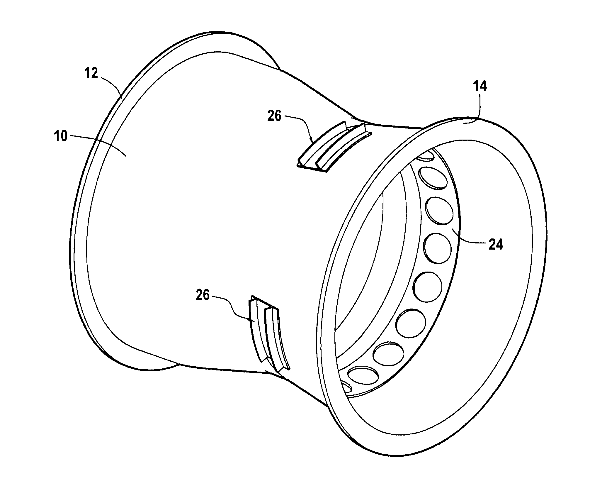
[0007]An object of the invention is to enable pieces of equipment, in particular relatively heavy pieces of equipment, to be fastened on an aeroengine fan casing when the casing is made of a composite material comprising fiber reinforcement densified by a matrix, while avoiding the above-mentioned drawbacks.
[0009]Thus, the composite material casing is held between the ring or ring sector and one or more equipment fastener parts, and it is less exposed to any risk of damage by the forces exerted on the fastener part(s).

Problems solved by technology

Nevertheless, mounting pieces of equipment on the casing can give rise to difficulty, particularly when the pieces of equipment are heavy and / or subjected to particular forces.
That solution is difficult or impossible to transpose to a fan casing that is made of composite material because of the high risk of severely damaging the composite material under the effect of the weight of the AGB and the members that it carries, and under the effect of the forces to which the AGB may be subjected in the event of exceptional loads being applied to the structure of the engine, in particular in the event of a fan blade breaking.
The forces, in particular shear or traction forces, that are generated in service by the presence of the equipment are thus transmitted to the casing with a high risk of the composite material of the casing being damaged.

Method used


Image

  • Aeroengine fan casing made of composite material, and a method of fabricating it
  • Aeroengine fan casing made of composite material, and a method of fabricating it
  • Aeroengine fan casing made of composite material, and a method of fabricating it

Examples


Embodiment Construction

[0022]The invention is described below with reference to its application to a turbomachine fan casing for an aeroengine.

[0023]As shown diagrammatically in FIG. 1, such a turbomachine comprises, from upstream to downstream in the flow direction of the gas stream: a fan 1 located at the inlet of the turbomachine; a compressor 2; a combustion chamber 3; a high-pressure (HP) turbine 4; and a low-pressure (LP) turbine 5. The turbines 4 and 5 are coupled respectively to the compressor 2 and to the fan 1 via coaxial HP and LP shafts (not shown). The turbomachine is housed in a casing comprising a plurality of portions corresponding to different ones of its elements. Thus, the fan 1 is surrounded by a fan casing 10 that carries various pieces of equipment on its outside face, in particular an AGB 8 that is mechanically connected to a shaft of the turbine.

[0024]FIGS. 2 and 3 show a fan casing 10 in accordance with the invention. The casing 10 is extended downstream by an intermediate casing ...


PUM

PropertyMeasurementUnit
thicknessaaaaaaaaaa
forcesaaaaaaaaaa
weightaaaaaaaaaa

Abstract

An aeroengine fan casing is made of composite material comprising fiber reinforcement densified by a matrix. The casing (10) is secured to at least one ring (24) or ring sector that is situated on the inside face of the casing and that is mechanically connected to an equipment fastener part (26) that is situated on the outside face of the casing, in particular for fastening an accessory gearbox.

Description

BACKGROUND OF THE INVENTION[0001]The invention relates to a gas turbine aeroengine fan casing, and more particularly to a fan casing made of composite material comprising fiber reinforcement densified by a matrix.[0002]In a gas turbine aeroengine, the fan casing performs several functions. It provides aerodynamic continuity for the secondary stream through the engine, it supports an abradable material facing the tips of the fan blades, it supports a structure that is generally in the form of acoustic panels in order to attenuate soundwaves at the inlet of the engine, and it incorporates or supports a shield for retaining debris projected against the inside face of the casing, such as ingested foreign bodies or damaged blade debris.[0003]Proposals have already been made to make a fan casing out of composite material. Document US 2008 / 206048, the content of which is incorporated herein by reference, describes a method comprising making a fiber preform for the casing by taking layers o...

Claims


Application Information

Patent Timeline
Patent Type & Authority Applications(United States)
IPC IPC(8): F01D25/24B29C45/14
CPCF01D21/045F05D2300/603Y02T50/672F02C7/32Y02T50/60B29B11/16
Inventor VERSEUX, PHILIPPESERVANT, REGIS EUGENE HENRI
Owner SN DETUDE & DE CONSTR DE MOTEURS DAVIATION S N E C M A
Learn More