
Devices, systems and methods for multimodal biosensing and imaging

a biosensor and imaging technology, applied in the field of medical imaging, can solve the problems of complex biomolecular or functional processes and structural features associated with healthy and diseased tissue, limited spatial resolution, and 1 cm

Inactive Publication Date: 2012-04-19
UNIV HOUSTON SYST
View PDF3 Cites 33 Cited by
  • Summary
  • Abstract
  • Description
  • Claims
  • Application Information

AI Technical Summary

Benefits of technology

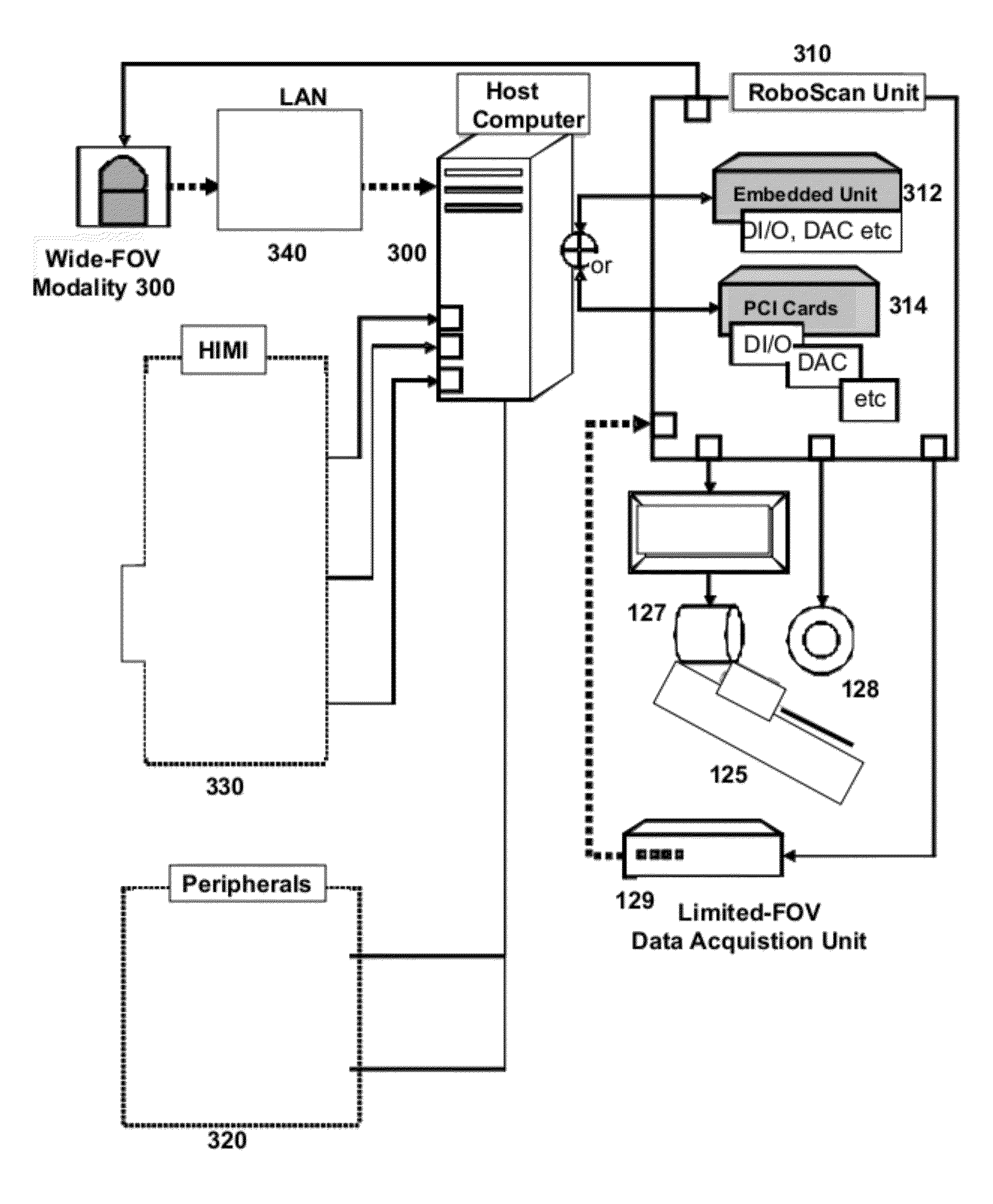
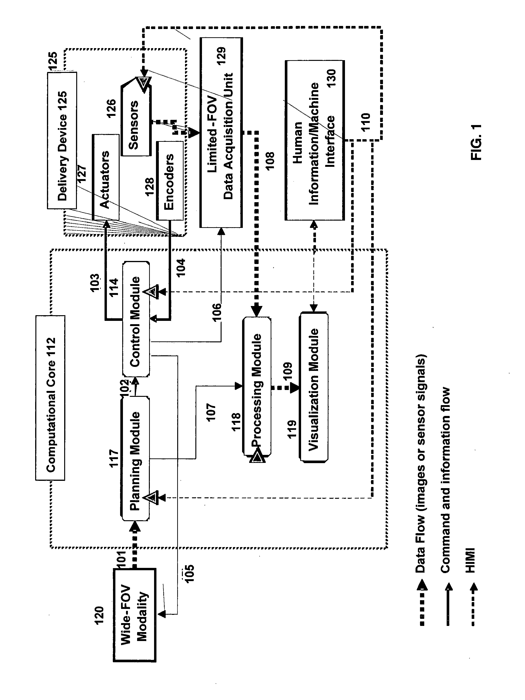
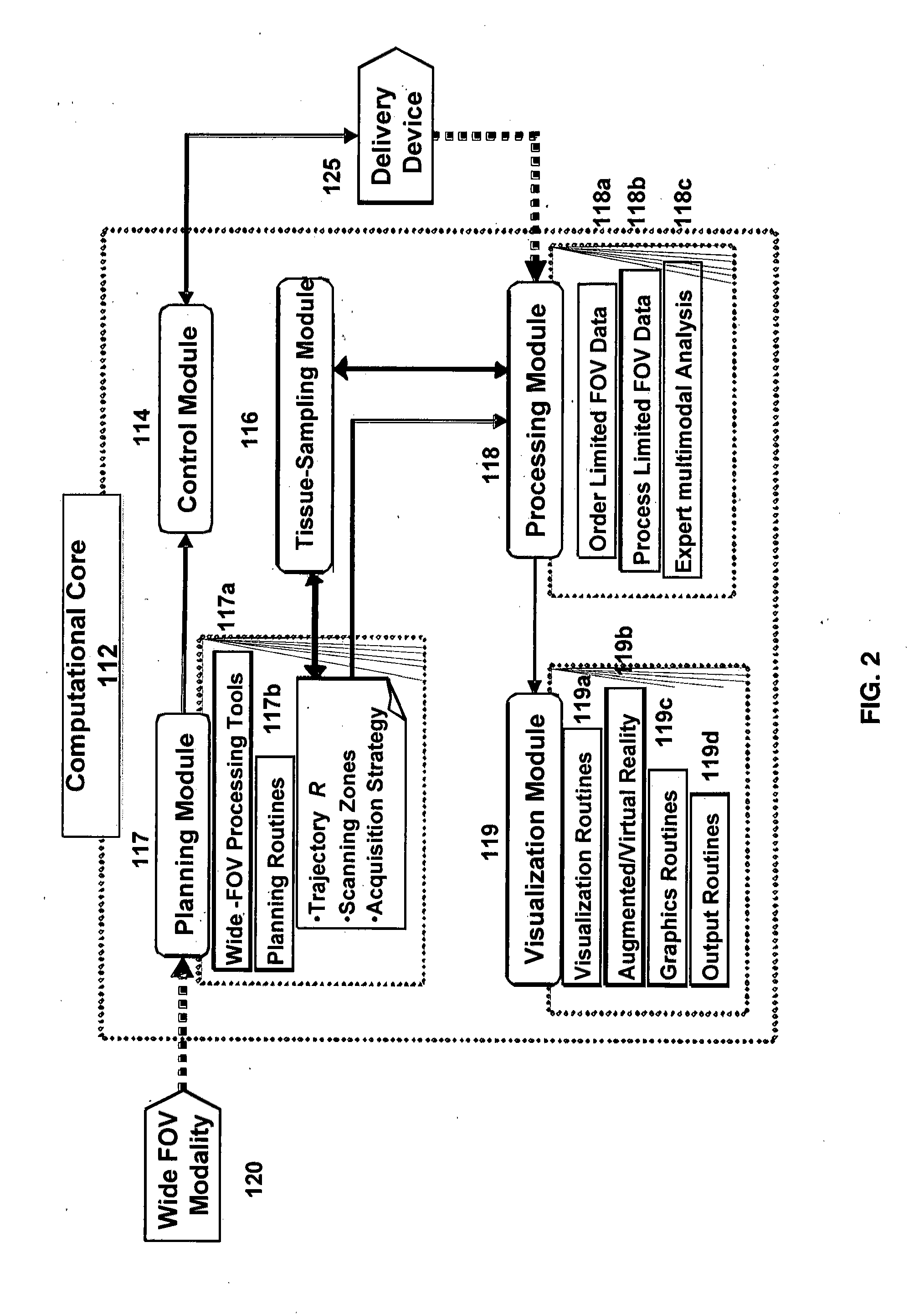
[0014]The present invention is directed to an automated system for multimodality imaging of a tissue in a subject. The system comprises a robotic delivery device configured for mechanically scanning the area of interest, a computational core comprising a plurality of software modules electronically interlinked with the delivery device, one or more interfaces between one or both of the computational core and the delivery device, at least one limited field of view sensor modality mechanically linked to or carried on the robotic delivery device and electronically linked to the computational core, and an operator thereof, and at least one wide field of view imaging modality electronically linked to the computational core. In a related automated systems, the robotic

Problems solved by technology

The biomolecular or functional processes and structural features associated with the healthy and diseased tissue are complex and occur, or their consequences manifested, at different levels of the living matter.
Although MRS can sense those species non-invasively and without contrast agents, it has limited spatial resolution (order of 1 cm) primarily due to the inherent low sensitivity of the nuclear magnetic resonance (NMR).
However, a major drawback of OCT, common to the high resolution or high sensitivity optical methods, is limited tissue penetration to about 2 mm.
Thus, the prior art is deficient the methods, device and system for multimodality and multi-level imaging, image-guided scanning and spectroscopy in situ.

Method used


Image

  • Devices, systems and methods for multimodal biosensing and imaging
  • Devices, systems and methods for multimodal biosensing and imaging
  • Devices, systems and methods for multimodal biosensing and imaging

Examples


example 1

Co-Registration of MRI and MRS

[0163]The essence of the proposed approach is the use of the actuated manipulator to mechanically couple and co-register the guiding, i.e., MRI, and the Limited-FOV, i.e., MRS, modalities. The adopted approach is based on the facts that the MR scanner has its inherent coordinate system defined by the resident magnetic field gradient coils and any MR signal generating entity can be imaged relative to this coordinate system.

[0164]Specifically, this is performed by registering an initial position of the probe to the MR coordinate system and then by calculating its transient position based on the known motion steps from the optical encoder. FIG. 20A shows the approach used for registering the RF coil and the miniature RF coil is used to collect an image (FIG. 20B) at the initial position. From this image the exact coordinate of the sensor can be extracted and if desired compared with the image collected with the large volume RF coil (FIG. 120C vs. FIG. 20D)...

example 2

Line Scan System

Data Collection

[0168]All MR studies are performed on a UNITY / NOVA (Varian, Palo Alto, Calif.) spectrometer imager system. The sample holder, that carries the phantom, is secured onto a custom-made base, the probe is inserted into the scanning channel, and the assembly is then inserted into the volume RF coil and secured onto the scanner's cradle. The cradle is positioned so the centre of the volume coil corresponded to the isocenter of the scanner, and then both the volume and the miniature RF coils are fine tuned and matched with the cradle in place. This or a similar set-up can be used in phantom, excised tissue and animal studies.

[0169]Studies are performed using two-compartment rectangular phantoms (39.6×44.6×89 mm3), one filled with a gelatin matrix and the other with commercially available vegetable oil. The sample holder, that carries the phantom, is secured onto the custom-made base, the probe is inserted into the scanning channel, and the assembly is then in...


PUM


Abstract

Provided herein are robotic or automated multimodal tissue scanning or imaging systems and methods. The systems comprise a robotic delivery device configured to mechanically scan one or more zones of a tissue by co-registering at least two modalities, i.e., one or more of each of a sensor modality and an imaging modality and acquiring sensor modality data at one or more positions in the zone(s) as the sensor modality is dimensionally translated along the device axes. The system also comprises a computational core of a plurality of interlinked modules for planning, processing, tissue-sampling, visualization, fusion, and control of the delivery device and the system. The methods provided herein utilize the automated systems to produce spatial maps based on the analyzed sensor modality data.

Description

CROSS-REFERENCES TO RELATED APPLICATIONS[0001]This non-provisional application claims benefit of provisional application U.S. Ser. No. 61 / 402,941, filed Sep. 8, 2010, now abandoned, the entirety of which is hereby incorporated by reference.GOVERNMENTAL SPONSORSHIP[0002]The U.S. Government has a paid-up license in this invention and the rights in limited circumstances to require the patent owners to license others on reasonable terms as provided for by the terms of grant No. CNS-0932272 awarded by the National Science Foundation.BACKGROUND OF THE INVENTION[0003]1. Field of the Invention[0004]The present invention relates to the field of medical imaging, particularly, multimodality imaging, and robotics. Specifically, the present invention relates to a method, device and system for performing multimodality imaging and / or biosensing for assessing the pathophysiology of tissue in situ for diagnostic, therapeutic, and interventional, including surgical, procedures, by means of an actuate...

Claims


Application Information

Patent Timeline
IPC IPC(8): A61B6/00A61B8/13A61M5/32A61B10/02A61B6/03A61M25/00A61B6/02A61B5/055
CPCA61B1/00172A61B5/055A61B5/062A61B5/064A61B6/03A61B8/0825A61B6/508A61B10/02A61B19/2203A61B19/52A61B6/4417A61B6/5247A61B8/5238A61B5/0035A61B90/36A61B34/30
Inventor TSEKOS, NIKOLAOS V.SONMEZ, AHMET E.
Owner UNIV HOUSTON SYST
Learn More