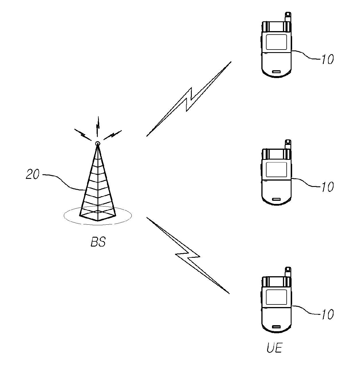

Power allocation method for wireless communication system, apparatus for same, and transceiver device using this form of signal transmission

a wireless communication system and power allocation technology, applied in the field of wireless communication system power allocation, can solve the problems of limited power, which can be used when data or signals are transmitted and received in the communication system, and achieve the effects of efficient power allocation, increased throughput, and maximum transmission capacity

Inactive Publication Date: 2012-04-19
PANTECH CO LTD
View PDF2 Cites 18 Cited by
  • Summary
  • Abstract
  • Description
  • Claims
  • Application Information

AI Technical Summary

Benefits of technology

[0007]The present disclosure provides a technology, which can increase throughput and efficiently allocate power to maximize a transmission capacity in a wireless communication system.
[0008]In accordance with an aspect of the present invention, there is provided a method of allocating power, including: acquiring at least one of reception power, a reception SINR, or a reception SNR of one or more receiving apparatuses based on virtual channel information generated by multiplying a precoding matrix and channel information; and allocating power for each stream such that the reception SINR is maximized.

Problems solved by technology

In general, power, which can be used when data or a signal is transmitted and received in a communication system, is limited.

Method used


Image

  • Power allocation method for wireless communication system, apparatus for same, and transceiver device using this form of signal transmission
  • Power allocation method for wireless communication system, apparatus for same, and transceiver device using this form of signal transmission
  • Power allocation method for wireless communication system, apparatus for same, and transceiver device using this form of signal transmission

Examples


Embodiment Construction

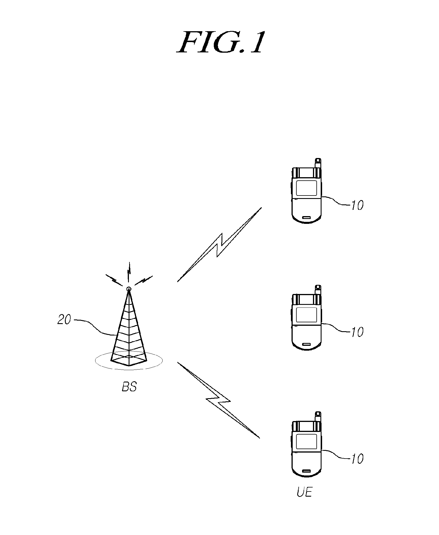
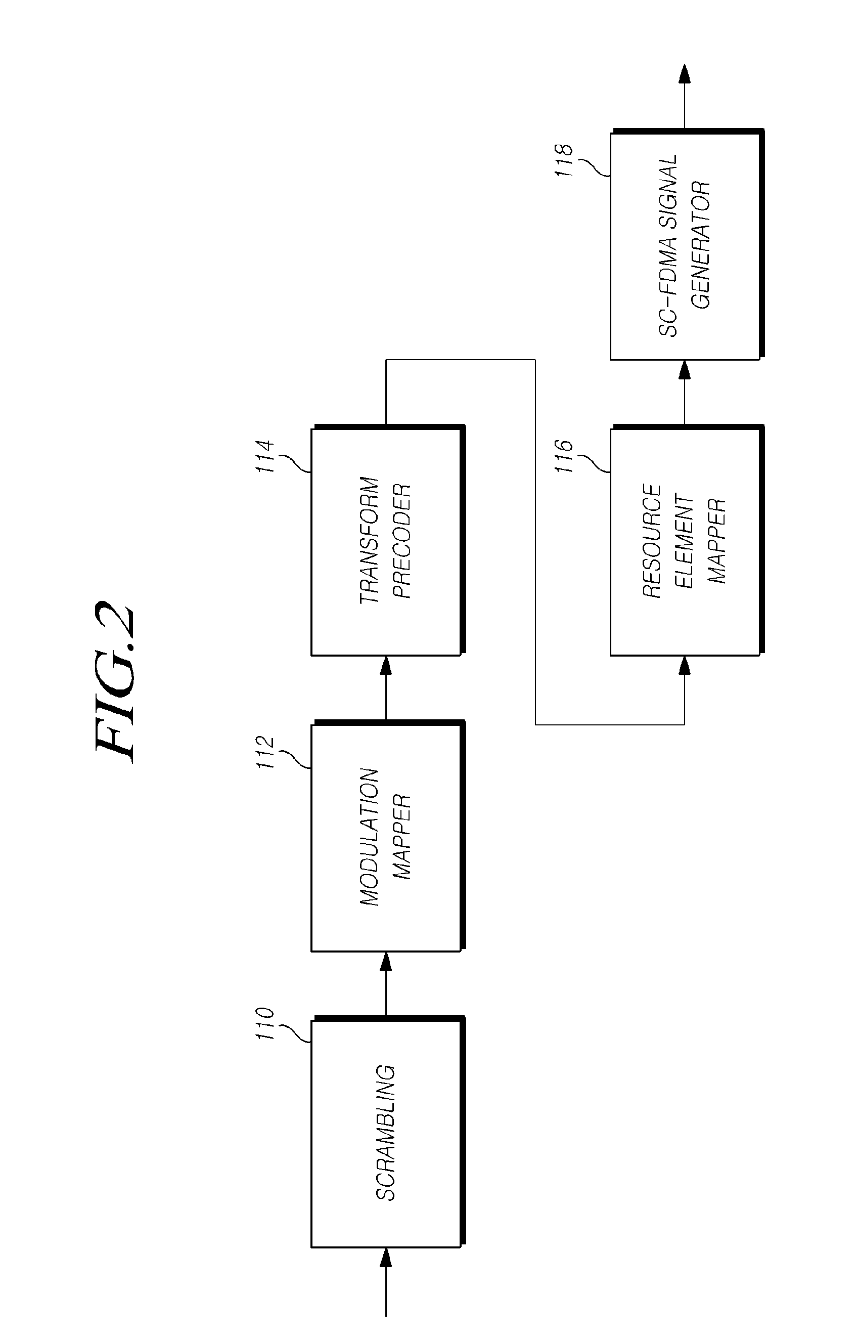
[0021]Hereinafter, exemplary embodiments of the present invention will be described with reference to the accompanying drawings. In the following description, the same elements will be designated by the same reference numerals although they are shown in different drawings. Further, in the following description of the present invention, a detailed description of known functions and configurations incorporated herein will be omitted when it may make the subject matter of the present invention rather unclear.

[0022]In addition, terms, such as first, second, A, B, (a), (b) or the like may be used herein when describing components of the present invention. Each of these terminologies is not used to define an essence, order or sequence of a corresponding component but used merely to distinguish the corresponding component from other component(s). It should be noted that if it is described in the specification that one component is “connected,”“coupled” or “joined” to another component, a t...


PUM


Abstract

Disclosed is a wireless communication system and a power allocation in the wireless communication system.

Description

CROSS-REFERENCE TO RELATED APPLICATION[0001]This application is the national Stage Entry of International Application PCT / KR2010 / 004075, filed on Jun. 23, 2010, and claims priority from and the benefit under 35 U.S.C. §119(a) of Korean Patent Application No. 10-2009-0056706, filed on Jun. 24, 2009, both of which are incorporated herein by reference for all purposes as if fully set forth herein.BACKGROUND[0002]1. Field[0003]The present invention relates to a wireless communication system, and more particularly to a power allocation in a wireless communication system.[0004]2. Discussion of the Background[0005]In general, power, which can be used when data or a signal is transmitted and received in a communication system, is limited.[0006]Accordingly, it is highly required to properly allocate power to transmit data or a signal.SUMMARY[0007]The present disclosure provides a technology, which can increase throughput and efficiently allocate power to maximize a transmission capacity in a...

Claims


Application Information

Patent Timeline
Patent Type & Authority Applications(United States)
IPC IPC(8): H04B15/00H04L1/02H04L25/49
CPCH04B7/0417H04B7/0443H04B7/0619Y02B60/50H04W52/42H04W72/0473H04W72/085H04W52/241H04W72/542Y02D30/70
Inventor PARK, KYOUNGMINKWON, KIBUMSUH, SUNG-JIN
Owner PANTECH CO LTD
Learn More