Wireless communication control method and wireless communication device
a control method and wireless communication technology, applied in the field of wireless communication control methods and wireless communication devices, can solve problems such as unadjusted, variety of transmission losses or delays
- Summary
- Abstract
- Description
- Claims
- Application Information
AI Technical Summary
Benefits of technology
Problems solved by technology
Method used
Image

Examples
first embodiment
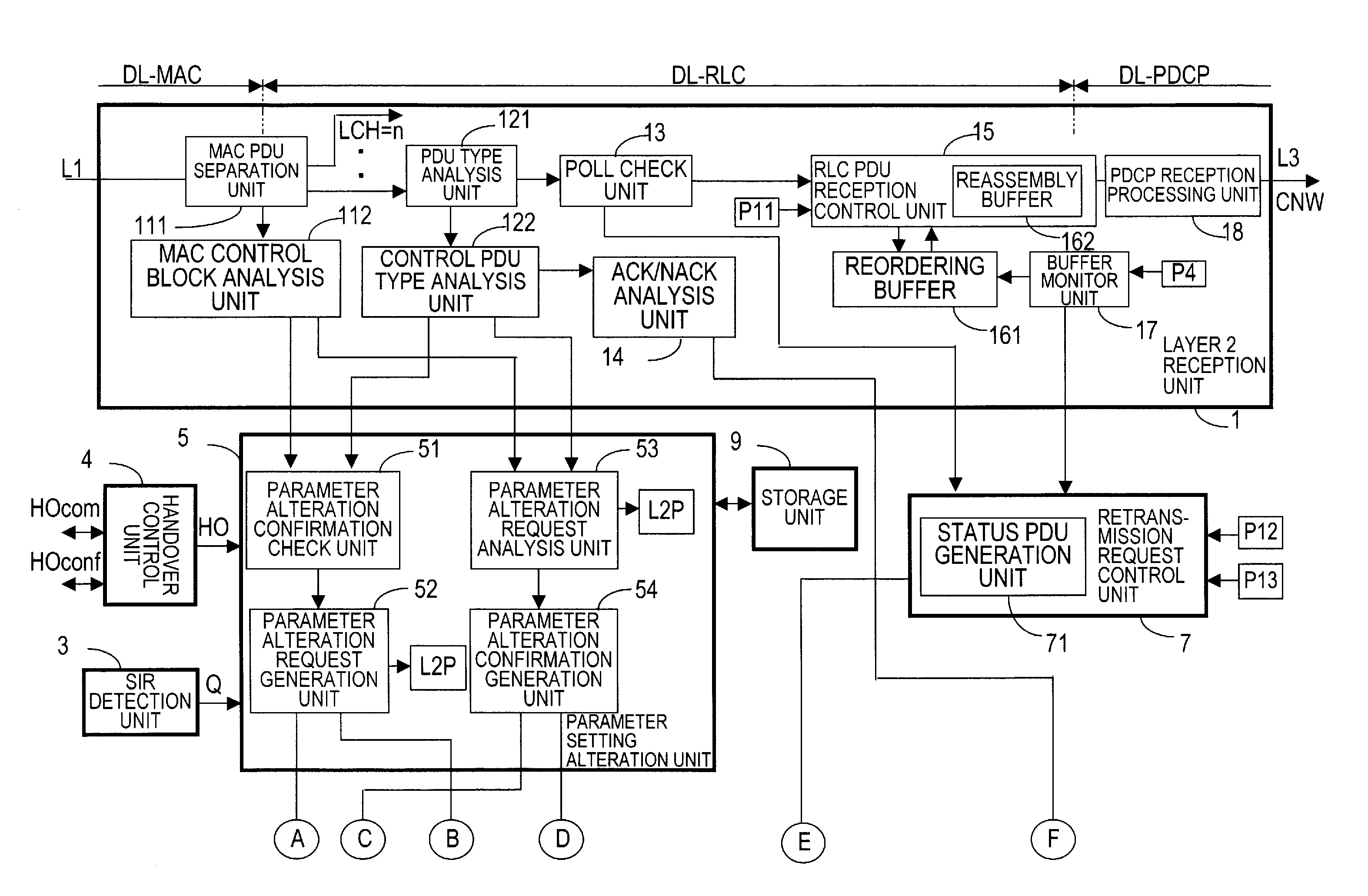
[0061]FIG. 4 is a block diagram which illustrates a configuration example of a function unit which performs reception processing in a function unit 430 (530) in a layer 2 illustrated in FIG. 2 and FIG. 3 of a wireless communication device in a first embodiment.
[0062]FIG. 5 is a block diagram which illustrates a configuration example of the function unit which performs transmission processing in the function unit 430 (530) in the layer 2 illustrated in FIG. 2 and FIG. 3 of the wireless communication device in the first embodiment. The function units illustrated in FIG. 4 and FIG. 5 are discretely connected to terminals A to F respectively.
[0063]As described above, the layer 2 function units 430 (530) in the wireless communication devices respectively mounted on the base station side and the mobile station side in a wireless communication system have almost the same configuration. Accordingly, FIG. 4 and FIG. 5 mainly illustrate the function units common to both of those stations. Her...
second embodiment
[0286]FIG. 20 is a block diagram showing a configuration example of a function unit which performs reception processing in a function unit 430 (530) in a layer 2 illustrated in FIG. 2 and FIG. 3 of a wireless communication device in the second embodiment.
[0287]FIG. 21 is a block diagram showing a configuration example of the function unit which performs transmission processing in the function unit 430 (530) in the layer 2 illustrated in FIG. 2 and FIG. 3 of the wireless communication device in the second embodiment. The function units illustrated in FIG. 20 and FIG. 21 are discretely connected to terminals A to H respectively.
[0288]The wireless communication device in the second embodiment illustrated in FIG. 20 and FIG. 21 is different from that in the first embodiment show in FIG. 4 and FIG. 5 in that it has a retransmission ratio measurement unit 8 in place of the SIR detection unit 3, in which the identical reference symbols are given to the identical or corresponding components...
PUM
 Abstract
Description
Claims
Application Information
 - R&D
- Intellectual Property
- Life Sciences
- Materials
- Tech Scout
- Unparalleled Data Quality
- Higher Quality Content
- 60% Fewer Hallucinations
Browse by: Latest US Patents, China's latest patents, Technical Efficacy Thesaurus, Application Domain, Technology Topic, Popular Technical Reports.
© 2025 PatSnap. All rights reserved.Legal|Privacy policy|Modern Slavery Act Transparency Statement|Sitemap|About US| Contact US: help@patsnap.com