
Electromechanical resonator with resonant anchor

a technology of electromechanical resonators and resonant anchors, applied in oscillator generators, instruments, computing, etc., to achieve the effect of low effective stiffness and greater design freedom

Active Publication Date: 2012-04-19
COMMISSARIAT A LENERGIE ATOMIQUE ET AUX ENERGIES ALTERNATIVES
View PDF9 Cites 23 Cited by
  • Summary
  • Abstract
  • Description
  • Claims
  • Application Information

AI Technical Summary

Benefits of technology

The invention proposes an electromechanical resonator that includes a suspended structure and an anchor structure for resonating at a given frequency. The anchor structure is designed to resonate at the same frequency as the suspended structure, and can be positioned at nodal points on the structure's resonance mode. The anchor structure can be made of a T-shaped element formed from a fixed beam and a second beam, which is coupled with the suspended structure and the substrate. The invention also includes a method for producing the resonator and a method for designing the suspended structure and anchor structure. The technical effects of the invention include improved resonance efficiency, reduced energy loss, and reduced stress on the structure.

Problems solved by technology

1) proposing external (lateral) anchors in order to continue to use as simple as possible a manufacturing method,
2) use of stiff anchors in order to obtain robust structures,
3) at the same time, favouring the movement of the structure, and also great mismatch of acoustic impedance between the structure and anchors in order to minimise the loss in the anchors. Acoustic impedance characterises the resistance which a medium opposes to its being moved when it is traversed by an acoustic wave. It is defined as the ratio of the acoustic pressure over the local speed of displacement in a medium. When an acoustic wave encounters the interface separating two different acoustic impedance media, a portion of the wave is transmitted into the other medium, whereas another portion is reflected from the interface. The notion of acoustic impedance enables this phenomenon to be studied completely and quantitatively, and also enables the quantities of acoustic energy transmitted and reflected to be estimated. In the case of the invention the aim is to minimise the transmitted energy. A great mismatch may be obtained by suddenly changing the transverse dimensions, or by using different materials.

Method used


Image

  • Electromechanical resonator with resonant anchor
  • Electromechanical resonator with resonant anchor
  • Electromechanical resonator with resonant anchor

Examples


first embodiment

[0064]FIGS. 9A to 9D illustrate the invention,

second embodiment

[0065]FIGS. 10A to 10G illustrate the invention.

DETAILED ACCOUNT OF PREFERRED EMBODIMENTS

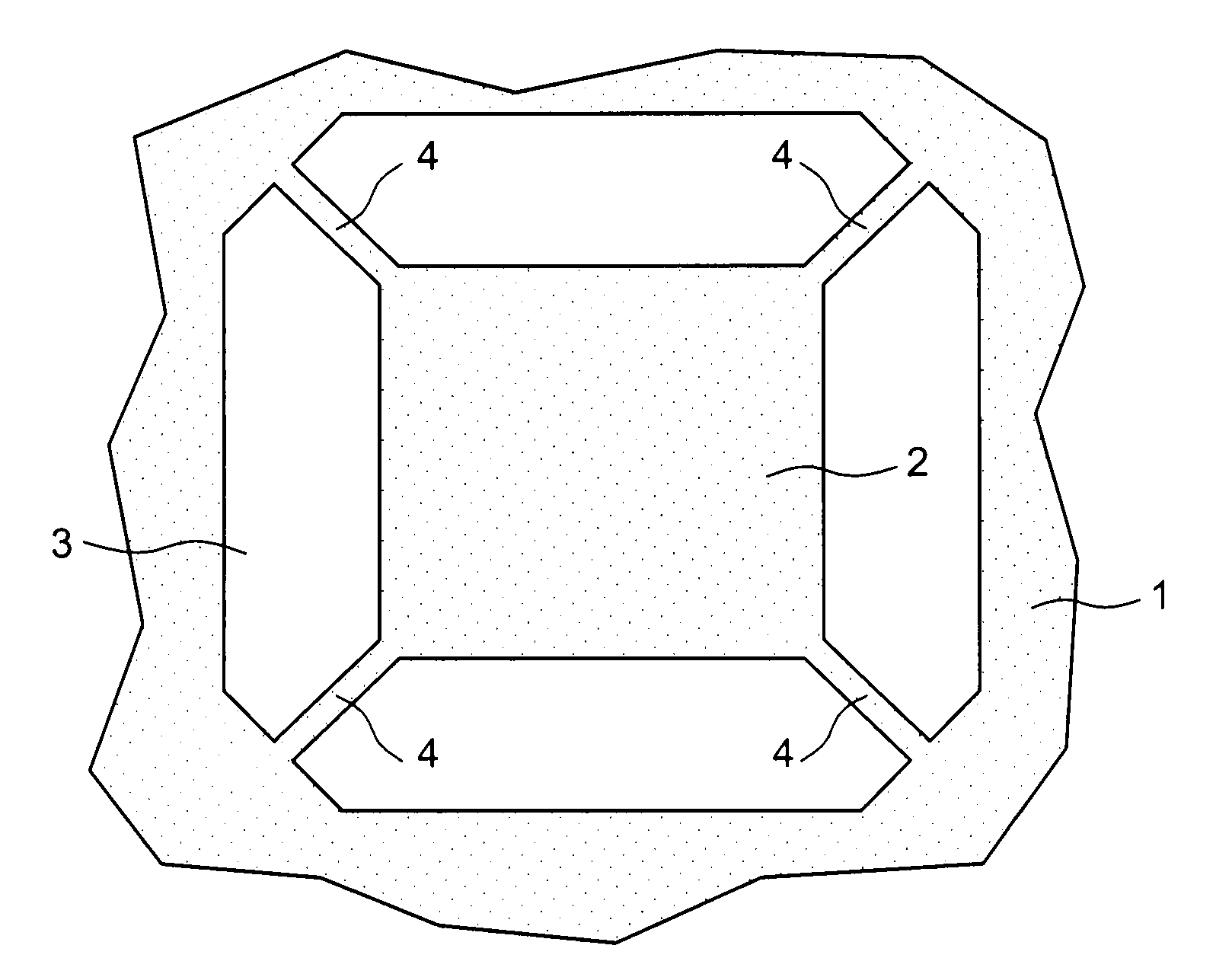
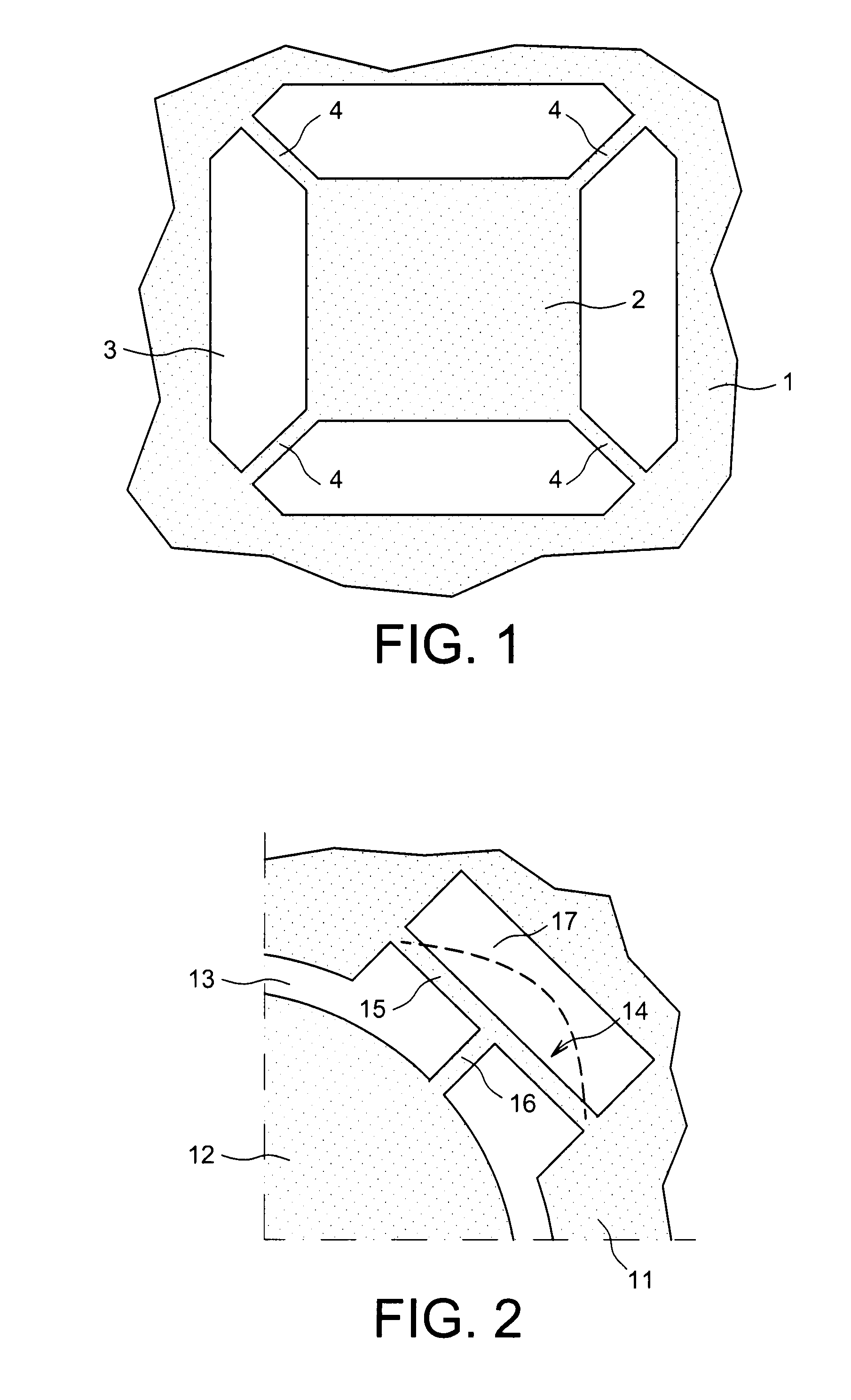
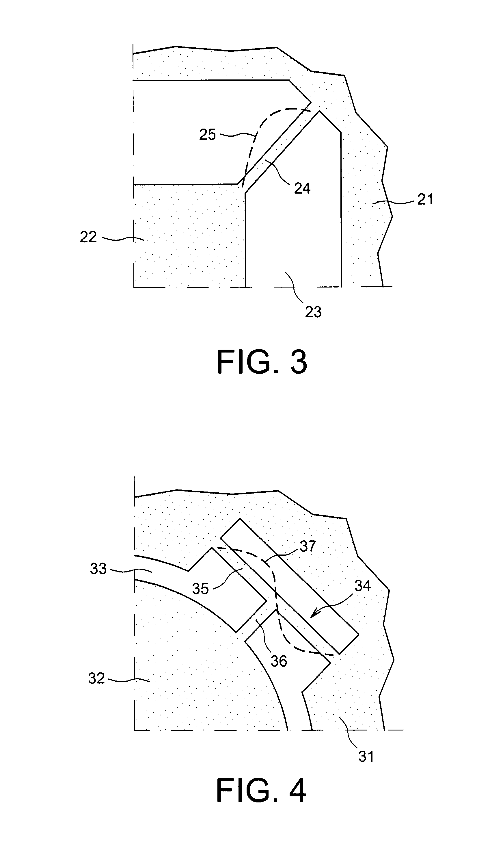
[0066]Generally, the oscillator according to the present invention includes the resonant structure proper generating the clock frequency, and an anchor structure which it is sought to cause to resonate at the same frequency as the resonant structure. The method of design of the resonator may be as follows:[0067]choice of the frequency of the clock signal to be generated,[0068]choice of the shape of the suspended structure (square, circular, ring-shaped, any shape, etc.),[0069]choice of the dimensions of the suspended structure in order that one of its natural modes is the chosen frequency,[0070]subsequent choice of the shape and position of the anchor structure which is to be made to resonate at the same frequency as the suspended structure,[0071]modelling of the suspended structure and of the anchor structure, to determine the dimensions of the anchor structure considered, in order that both st...


PUM


Abstract

An electromechanical resonator produced on a substrate, and a method of producing thereof, including: a suspended structure produced at least partly from the substrate, configured to have a vibration imparted to it such that it resonates at least one natural resonance frequency of the suspended structure; an anchor structure to anchor the suspended structure, by at least one area of its periphery, to the remainder of the substrate, and dimensioned to resonate at the resonance frequency; a mechanism to excite the suspended structure, to cause it to vibrate at the resonance frequency; and a mechanism to detect the vibration frequency of the suspended structure.

Description

TECHNICAL FIELD[0001]The invention relates to an integrated electromechanical resonator on a substrate. The mobile portion of the resonator, i.e. the suspended portion, is connected to the fixed portion (the remainder of the substrate) by anchors which are resonant according to the invention. Generally, such resonators can be used as an oscillating structure for a time base, notably in the field of microcomputing, mobile telephony and other mobile devices. They can also be used to produce resonant sensors, in particular for mass sensors, gas sensors or biological sensors.STATE OF THE PRIOR ART[0002]All current microelectronic circuits require a clock in order to operate. This clock consists of an oscillator and its associated electronics. The oscillator is a mechanical structure, called a resonator, which is kept vibrating in one of its natural modes, and fed back to itself via the associated electronics by virtue of actuation and detection means, generating by this means a signal w...

Claims


Application Information

Patent Timeline
Patent Type & Authority Applications(United States)
IPC IPC(8): H03B1/00G06F17/50
CPCH03H9/02338H03H9/2436H03H2009/02503H03H2009/0244H03H2009/02385H03H3/0072H03H2009/2442H03H2009/02527
Inventor HENTZ, SEBASTIENARCAMONE, JULIEN
Owner COMMISSARIAT A LENERGIE ATOMIQUE ET AUX ENERGIES ALTERNATIVES
Learn More