
Rotationally Controlled Cosmetic Powder Dose Dispenser

a dispenser and rotational control technology, applied in the direction of packaging foodstuffs, transportation and packaging, packaged goods types, etc., can solve the problems of cosmetic product leakage or spillage, powder is often not dispensed at a controlled rate, and the device has many drawbacks, so as to achieve the effect of level of predictability

Active Publication Date: 2012-04-19
HCP PACKAGING USA
View PDF13 Cites 9 Cited by
  • Summary
  • Abstract
  • Description
  • Claims
  • Application Information

AI Technical Summary

Benefits of technology

[0006]The present invention is thus founded on the basic object of providing a cosmetic powder dispenser that dispenses doses of cosmetic powder conveniently, efficiently, and with a level of predictability.
[0007]A further object of embodiments of the invention is to provide a cosmetic powder dose dispenser that dispenses doses of cosmetic powder with reduced messiness.
[0008]Another object of embodiments of the invention is to provide a cosmetic powder dose dispenser that dispenses doses of cosmetic powder with minimal waste of cosmetic product.
[0009]Yet another object of embodiments of the invention is to provide a cosmetic powder dose dispenser that can dispense multiple doses of cosmetic powder without a need for excessive manipulation of the dispenser.
[0010]An additional object of embodiments of the invention is to provide a cosmetic powder dose dispenser that is portable and easy to use.
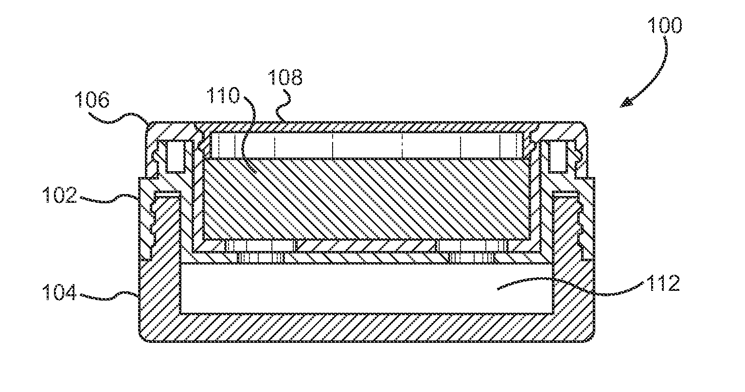
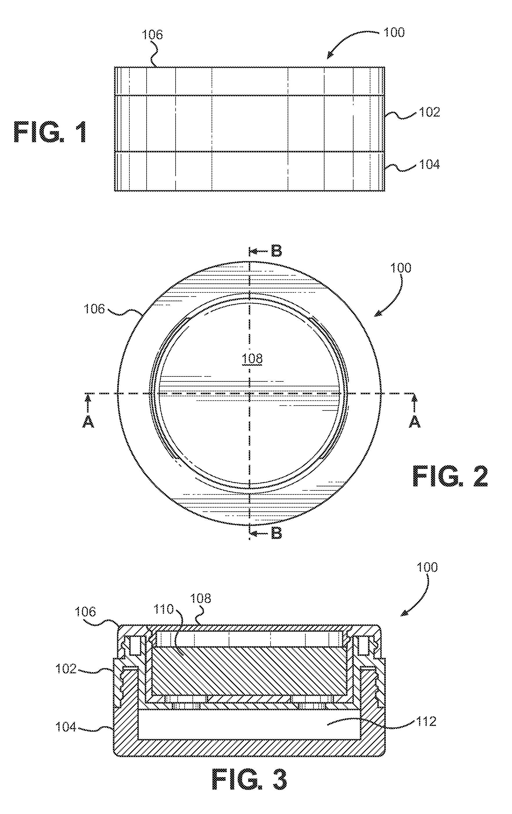
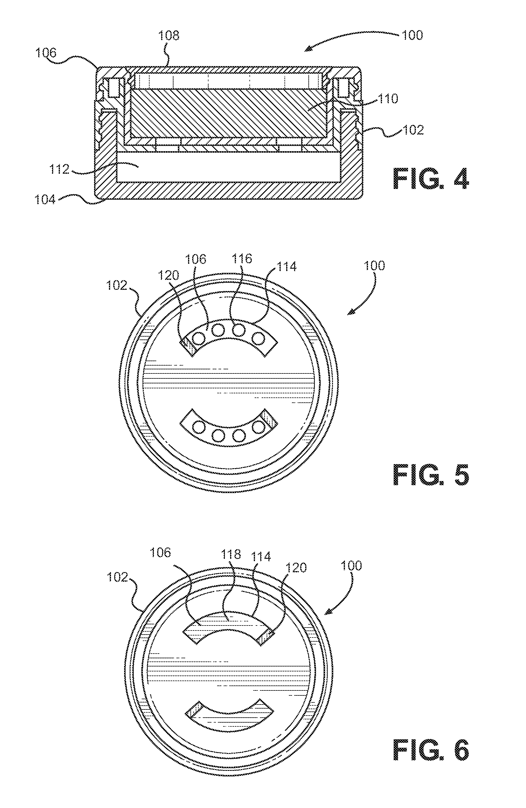
[0013]In carrying forth the foregoing objects, an embodiment of the present invention for a rotationally controlled cosmetic powder dose dispenser employs a sifter housing in combination with a sifter cup pivotally retained by the sifter housing to retain and dispense a volume of cosmetic powder from the open inner volume of the sifter cup into a sifter jar that is removably coupled to the sifter housing. At least one aperture is disposed in the bottom wall of the sifter housing and at least one aperture is disposed in the bottom wall of the sifter cup. The at least one aperture in the bottom wall of the sifter cup can be selectively disposed in alignment with the at least one aperture in the bottom wall of the sifter housing to permit a volume of cosmetic powder to be dispensed from the open inner volume of the sifter cup. The at least one aperture in the bottom wall of the sifter cup can be selectively disposed out of alignment with the at least one aperture in the bottom wall of the sifter housing to prevent cosmetic powder from being dispensed from the open inner volume of the sifter cup. The sifter jar has an open inner volume for receiving the cosmetic powder dispensed from the open inner volume of the sifter cup. A cap can be selectively engaged with the sifter cup to retain cosmetic powder in the open inner volume of the sifter cup.

Problems solved by technology

Historically, these devices have many drawbacks, which have been recognized in the art.
For example, powder is often not dispensed at a controlled rate, allowing either too little or too much powder to be emitted with each dispensing operation.
Another common problem under the prior art is the tendency dispensing devices to allow product to continue to flow even after the desired amount of product has been dispensed.
Consequently, cosmetic product may leak or spill out of the device, particularly during transportation from one location to another as is necessary for permitting reapplication during a given day or evening.
This unintentional dispensing of the potentially valuable cosmetic powder results in wasted cosmetic product and messiness.

Method used


Image

  • Rotationally Controlled Cosmetic Powder Dose Dispenser
  • Rotationally Controlled Cosmetic Powder Dose Dispenser
  • Rotationally Controlled Cosmetic Powder Dose Dispenser

Examples


Embodiment Construction

[0045]It will be appreciated that the rotationally controlled cosmetic powder dose dispenser disclosed herein is subject to widely varied embodiments. However, to ensure that one skilled in the art will be able to understand and, in appropriate cases, practice the present invention, certain preferred embodiments of the broader invention revealed herein are described below and shown in the accompanying drawing figures.

[0046]It will be appreciated that the present discussion relates primarily to devices for enabling the retention and dispensing of cosmetic powders. However, the dispenser device disclosed herein is not so limited. It may find useful application in other industries beyond the field of cosmetics. The protection afforded the invention should be limited only as may be expressly required by the claims.

[0047]Looking more particularly to the drawings, an embodiment of the cosmetic powder dose dispenser disclosed herein is indicated generally at 100 in FIGS. 1 through 6. There...


PUM


Abstract

A rotationally controlled cosmetic powder dose dispenser with a sifter cup pivotally retained by a sifter housing. Opposed arcuate slots are disposed in the bottom wall of the sifter housing and first and second series of apertures are disposed in opposed arcuate configurations in the bottom wall of the sifter cup. The series of apertures and the arcuate slots can be selectively aligned to dispense a volume of cosmetic powder into a sifter jar that is removably coupled to the sifter housing. The sifter housing has a rim received between an outer cylindrical wall and a peripheral wall of the sifter cup, and the sifter jar has a rim received between an outer cylindrical wall and a peripheral wall of the sifter housing in a threaded engagement.

Description

PRIORITY[0001]Provisional Application No. 61 / 299,205, filed Jan. 28, 2010, and Provisional Application No. 61 / 382,983, filed Sep. 15, 2010FIELD OF THE INVENTION[0002]The present invention relates generally to cosmetic dispensers. More particularly, disclosed herein is a cosmetic powder dispenser that retains cosmetic powder within a housing and selectively dispenses powder in doses.BACKGROUND OF THE INVENTION[0003]Numerous cosmetic powder dispensers have been disclosed by the prior art. Devices have been taught where a jar that simply retains a volume of powder. Other devices include a sifter with the goal of controlling the flow of powder from an inner volume of the dispenser. Historically, these devices have many drawbacks, which have been recognized in the art.[0004]For example, powder is often not dispensed at a controlled rate, allowing either too little or too much powder to be emitted with each dispensing operation. Another common problem under the prior art is the tendency d...

Claims


Application Information

Patent Timeline
Patent Type & Authority Applications(United States)
IPC IPC(8): A45D33/02
CPCA45D33/02A45D33/16A45D33/08
Inventor HOLLOWAY, THOMAS F.
Owner HCP PACKAGING USA
Learn More