
Terminal device, wireless communication system, and wireless communication method

a technology of wireless communication system and terminal device, applied in the direction of wireless communication, network data management, electrical equipment, etc., can solve the problems of wasting wireless resources, unable to connect to terminal device henb, and taking more time to detect cgi, so as to prevent communication interruption and control waste of wireless resources

Active Publication Date: 2012-04-12
PANASONIC INTELLECTUAL PROPERTY CORP OF AMERICA
View PDF2 Cites 6 Cited by
  • Summary
  • Abstract
  • Description
  • Claims
  • Application Information

AI Technical Summary

Benefits of technology

[0020]Another aspect of the present invention is a wireless communication system, and this wireless communication system is a wireless communication system comprising a terminal device possessed by a user and a base station apparatus installed in a base station of a macrocell, wherein the terminal device is configured to be provided with: a trigger judging section judging, on the basis of a result of comparison between a reception quality of the macrocell and a reception quality of a small cell in the macrocell, whether an event trigger for performing handover from the macrocell to the small cell has occurred or not; a first measurement result reporting section transmitting a first measurement result report which includes a physical cell ID indicating a small cell for which the event trigger has occurred, to a base station apparatus of the macrocell; a proper cell ID detecting section detecting a proper cell ID for uniquely identifying the small cell for which the event trigger has occurred, on the basis of measurement setting information transmitted from the base station apparatus of the macrocell as a response to the first measurement result report; a second measurement result reporting section transmitting a second measurement result report which includes the detected proper cell ID, to the base station apparatus of the macrocell; and a report transmission controlling section controlling, on the basis of a reception quality of a first small cell for which an event trigger has occurred earlier and a reception quality of a second small cell for which an event trigger has occurred later, transmission of the first and second measurement result reports of the first and second small cells so as to reduce the frequency of transmission of the measurement result reports when the event triggers have continuously occurred.
[0021]Another aspect of the present invention is a wireless communication method, and the wireless communication system includes: judging, on the basis of a result of comparison between a reception quality of a macrocell and a reception quality of a small cell in the macrocell, whether an event trigger for performing handover from the macrocell to the small cell has occurred or not; transmitting a first measurement result report which includes a physical cell ID indicating a small cell for which the event trigger has occurred, to a base station of the macrocell; detecting a proper cell ID for uniquely identifying the small cell for which the event trigger has occurred, on the basis of measurement setting information transmitted from the base station of the macrocell as a response to the first measurement result report; transmitting a second measurement result report which includes the detected proper cell ID, to the base station of the macrocell; and controlling, on the basis of a reception quality of a first small cell for which an event trigger has occurred earlier and a reception quality of a second small cell for which an event trigger has occurred later, transmission of the first and second measurement result reports of the first and second small cells so as to reduce the frequency of transmission of the measurement result reports when the event triggers have continuously occurred.
[0022]The present invention is capable of preventing measurement result reports from being frequently transmitted from a terminal device to the base station of a macrocell, controlling waste of wireless resources, preventing detection of a proper cell ID from being frequently performed and preventing communication interruption from frequently occurring.

Problems solved by technology

Therefore, even if detecting an HeNB with a good reception quality, the terminal device cannot connect to the HeNB if the terminal is not permitted to access the HeNB (except for the case of emergency).
However, there are not so many cells that can be identified by a PCI.
In this case, however, if the above-stated PCI collision occurs, there is a possibility that the eNB of the serving cell transmits the handover request to the HeNB of a wrong CSG cell (this is called PCI confusion) as shown in FIG. 12.
However, it takes more time to detect a CGI (in comparison with a PCI).
If a terminal device passes through such an area, the reception quality of the macrocell is low (because the terminal device is located at the cell edge of the macrocell), and there is a strong possibility that an event trigger for a nearby CSG cell occurs.
Furthermore, in this case, since the multiple HeNBs are adjacently arranged, there is a possibility that an event trigger for another CSG cell is caused only by the terminal device moving a little.
That is, in such a case, there is a possibility that event triggers for the multiple CSG cells continuously occur.
As described above, when event triggers for multiple CSG cells continuously occur, measurement result reports are frequently transmitted from a terminal device to an eNB, and wireless resources are wasted.
Furthermore, if CGI detection is frequently performed, communication is frequently interrupted.

Method used


Image

  • Terminal device, wireless communication system, and wireless communication method
  • Terminal device, wireless communication system, and wireless communication method
  • Terminal device, wireless communication system, and wireless communication method

Examples


first embodiment

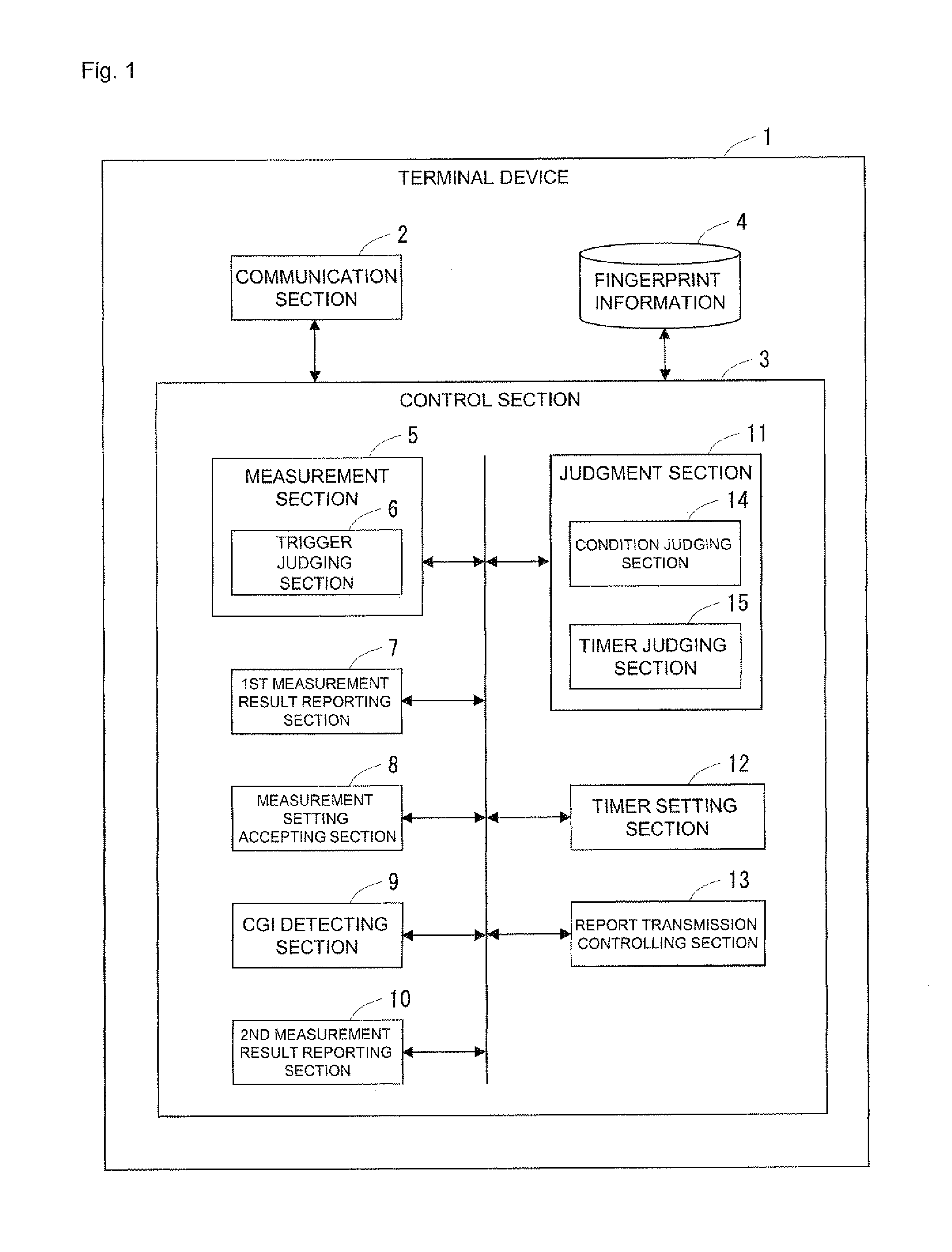
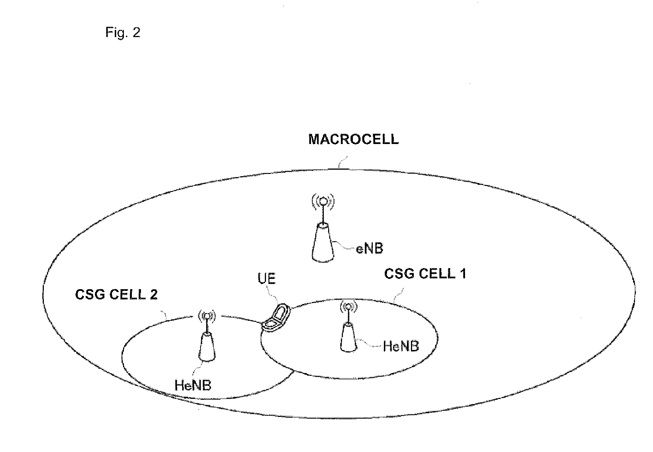
[0041]The configuration of a terminal device of a first embodiment of the present invention will be described with reference to drawings. FIG. 1 is a block diagram showing the configuration of the terminal device of this embodiment, and FIG. 2 is a diagram showing an example of arrangement of the terminal device, a macrocell base station and CSG cell base stations in a wireless communication system.

[0042]Here, the cell arrangement of this embodiment will be described first with reference to FIG. 2. As shown in FIG. 2, the wireless communication system of this embodiment is provided with a terminal apparatus (UE), a macrocell base station (eNB) constructing a macrocell and home base stations (HeNBs) constructing CSG cells installed in the macrocell. In the example in FIG. 2, there is shown a case where two CSG cells exist around the terminal device located at a macrocell edge. Here, the CSG cell corresponds to a small cell of the present invention. Though FIG. 2 shows a case where th...

second embodiment

[0086]Next, a terminal device of a second embodiment of the present invention will be described. Here, description will be made mainly on points in which the terminal device of the second embodiment is different from the first embodiment. The components and operations of this embodiment are similar to those of the first embodiment unless especially otherwise referred to.

[0087]FIG. 9 is a block diagram showing the configuration of the terminal device of this embodiment. A terminal device 20 of this embodiment is equipped with a function of using finger print information. Therefore, the terminal device 20 is not provided with the fingerprint information storing section 4 for holding fingerprint information. A condition judging section 21 of this embodiment judges whether a predetermined condition to be a criteria at the time of performing measurement result report transmission control is satisfied or not only on the basis of the reception quality of a CSG cell for which an event trigg...


PUM


Abstract

A terminal device (1) is provided with: a trigger judging section (6) judging whether an event trigger for performing handover from a macrocell to a CSG cell has occurred or not; a first measurement result reporting section (7) transmitting a first measurement result report which includes the PCI of a CSG cell for which an event trigger has occurred, to an eNB; a CGI detecting section (9) detecting the CGI of the CSG cell for which the event trigger has occurred, on the basis of measurement setting information transmitted from the eNB; and a second measurement result reporting section (10) transmitting a second measurement result report which includes the detected CGI, to the eNB. When event triggers have continuously occurred, a report transmission controlling section (13) controls transmission of the measurement result reports on the basis of the reception qualities of the CSG cells to reduce the frequency of transmission of the measurement result reports. Thereby, it is possible to control waste of wireless resources and prevent communication interruption from frequently occurring.

Description

TECHNICAL FIELD[0001]The present invention relates to a terminal device used in a wireless communication system, and in particular to a technique for handover from a macrocell to a CSG cell.BACKGROUND ART[0002]Recently, it has been examined by the 3GPP to construct a small cell (a CSG cell) by installing an indoor home base station (HeNB) in a cell (a macrocell) constructed by an ordinary base station (eNB) (see FIG. 11). The HeNB has a function of restricting terminal devices (UEs) which can access the HeNB, and a terminal device can connect to only an HeNB that it is permitted to access. Therefore, even if detecting an HeNB with a good reception quality, the terminal device cannot connect to the HeNB if the terminal is not permitted to access the HeNB (except for the case of emergency).[0003]In order for the terminal device to obtain permission to access an HeNB, the terminal device needs to confirm cell identification information (a cell ID) included in notification information t...

Claims


Application Information

Patent Timeline
Patent Type & Authority Applications(United States)
IPC IPC(8): H04W36/00H04W24/00
CPCH04W8/26H04W24/10H04W88/08H04W88/02H04W36/08H04W36/0085H04W36/0058
Inventor MATSUO, HIDENORIAOYAMA, TAKAHISAHIRANO, JUN
Owner PANASONIC INTELLECTUAL PROPERTY CORP OF AMERICA
Learn More