Method for Estimating Kinetic Rates

a kinetic rate and rate technology, applied in chemical methods analysis, chemical property prediction, instruments, etc., can solve the problem of unsuitable replication of downstream spots

Active Publication Date: 2012-04-05
PHADIA AB
View PDF1 Cites 2 Cited by
  • Summary
  • Abstract
  • Description
  • Claims
  • Application Information

AI Technical Summary

Benefits of technology

[0006]The present invention relates to a method for estimating or determining kinetic characteristics such as kon- and koff-rates. The method could be used in a microassay device for screening or ranking of markers or affinity binders, for exampl...

Problems solved by technology

However the depletion of reactant in upstream spots, resulting in downstream spots displaying lower level...

Method used


Image

  • Method for Estimating Kinetic Rates
  • Method for Estimating Kinetic Rates
  • Method for Estimating Kinetic Rates

Examples


examples

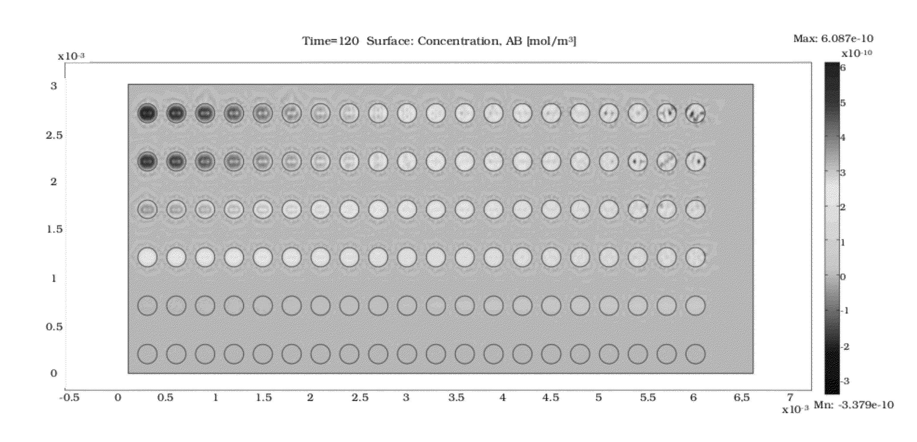
[0045]As surface material for the microarray printing, Millipore HF090MC100 nitrocellulose strips are used. The strips are pre-fabricated with a cardboard backing and are cut into smaller segments of 1 cm width and 3 cm in length (FIG. 1). The thickness of the membrane is approximately 135 μm. A consumer-grade glue (“Skollim”, Casco) is used to attach the strips to the glass slide support. For printing, a Nanoplotter 1.2 (Gesim) is used, and one drop of approximately 300 pL is deposited in each spot, producing arrays with proteins with high affinity, for example antibodies such as Affibody™ molecules, in rows with 40 downstream identical spots for each binder. After spotting the arrays, the slides are kept in room temperature during 24 hours before used for assays. Prior to performing the assay, a stretch of industrial grease (Spezialfett #3500, Heraeus) of approximately 2 mm width and 2 mm thickness is applied on one end of the strip to create a hydrophobic barrier, with room for a...


PUM


Abstract

The present invention relates to a method for estimation of kinetic characteristics for the formation and dissociation of a complex using lateral flow. The present invention facilitates an easy to use method with high accuracy.

Description

TECHNICAL FIELD[0001]The present invention relates to a method for estimating kinetic on- and off-rates.BACKGROUND[0002]Lateral flow assay systems have been extensively used as laboratory and point of care devices over the past forty or more years for clinical diagnosis of a wide variety of physiological conditions and disease states. The popularity stems mainly from such inherent useful characteristics as short assay times, high portability, convenient read-out options, ease-of-use, low cost, and often sufficient diagnostic accuracy.[0003]Microarrays are powerful tools for sensitive multi-parameter biochemical analysis. Recently, it has been demonstrated that microarrays printed onto nitrocellulose substrates can be employed for multiplexed lateral flow analysis. While multiplexed lateral flow assays could prove valuable for instance in comprehensive on-site diagnostic devices, immunochromatography as it is employed in lateral flow assays presents very different conditions for anal...

Claims


Application Information

Patent Timeline
IPC IPC(8): G06F19/00G16C20/30
CPCG01N33/557G06F19/70G01N33/558G16C99/00G16C20/30G01N33/54388
Inventor GANTELIUS, JESPERNYSTRAND, MATSANDERSSON-SVAHN, HELENE
Owner PHADIA AB
Why Eureka
Try Eureka