
Method and apparatus for a LED driver with high power factor

a technology of led drivers and power factors, applied in the field of led drivers, can solve the problems of low voltage vsub>dc /sub>, distortion of input current isub>dc /sub>, and poor power factor, and achieve the effect of improving the reliability of led drivers

Active Publication Date: 2012-04-05
SEMICON COMPONENTS IND LLC
View PDF10 Cites 20 Cited by
  • Summary
  • Abstract
  • Description
  • Claims
  • Application Information

AI Technical Summary

Benefits of technology

[0010]It is an objective of the present invention to provide a control circuit and a control method for LED driver. It can eliminate the need of the input capacitor for improving the reliability of the LED driver.
[0011]It is an objective of the present invention to provide a control circuit and a control method for LED driver. It can control the LED driver to provide output regulation without input capacitor for improving the power factor, reducing the size and the cost of the LED driver.
[0012]It is an objective of the present invention to provide a control circuit and a control method for LED driver. It can control the LED driver to provide the constant current for driving the LED.

Problems solved by technology

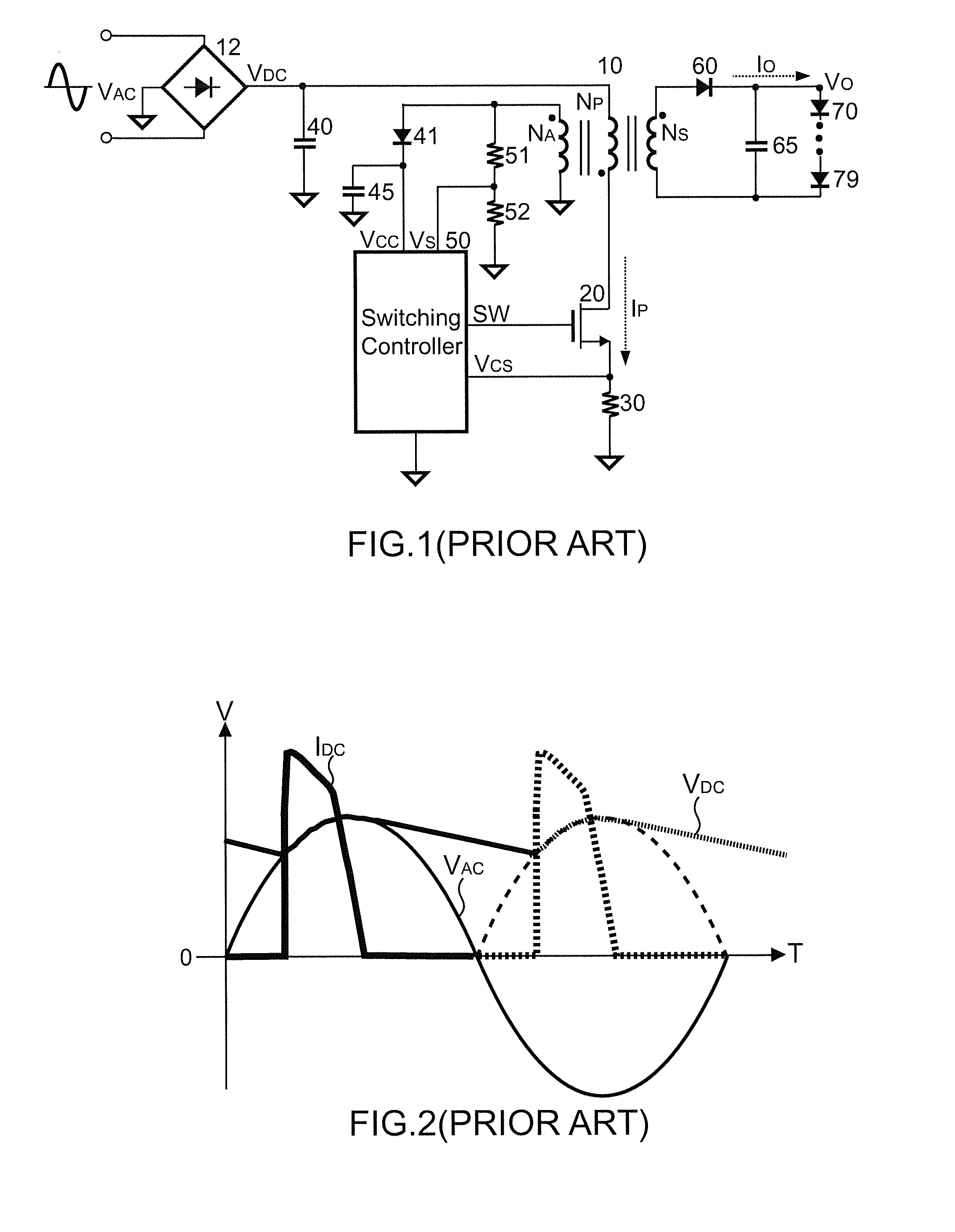
However, the input electrolytic capacitor 40 causes the distortion of an input current IDC and generate poor power factor (PF).
However, without the input electrolytic capacitor 40 will cause the voltage VDC to be low.
Besides, the input electrolytic capacitor 40 is an electrolytic capacitor that is bulky and low reliability.

Method used


Image

  • Method and apparatus for a LED driver with high power factor
  • Method and apparatus for a LED driver with high power factor
  • Method and apparatus for a LED driver with high power factor

Examples


Embodiment Construction

[0026]The following description is of the best-contemplated mode of carrying out the invention. This description is made for the purpose of illustrating the general principles of the invention and should not be taken in a limiting sense. The scope of the invention is best determined by reference to the appended claims.

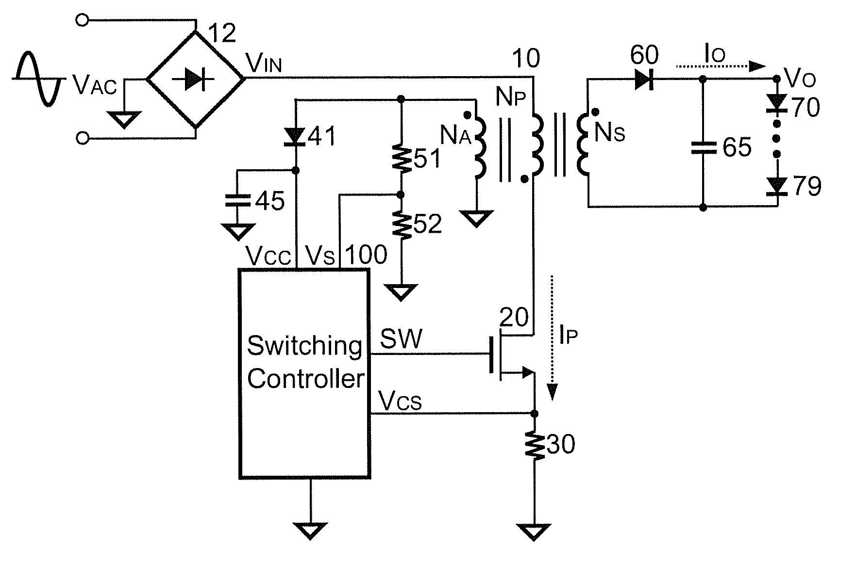
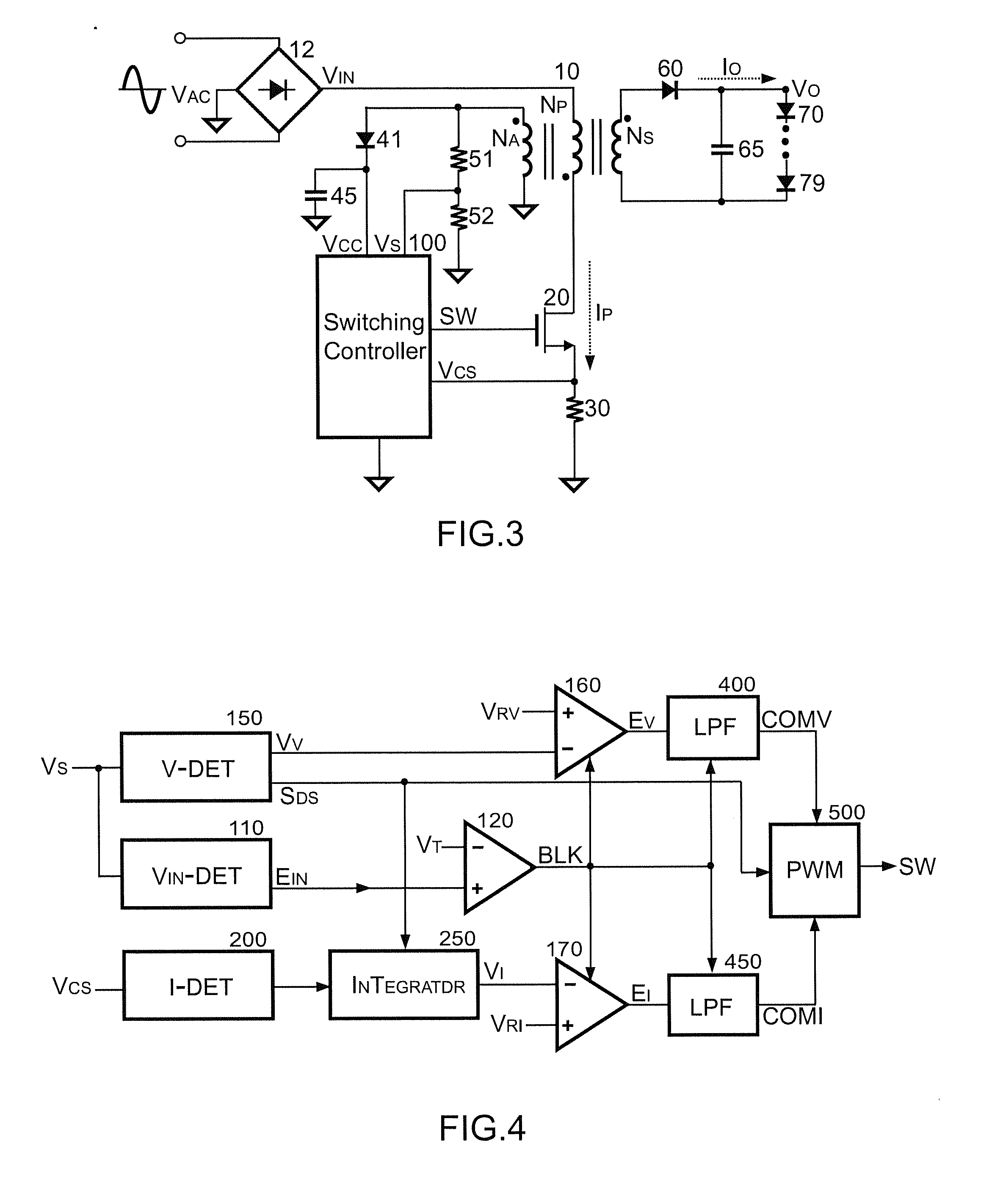
[0027]FIG. 3 is a preferred embodiment of the present invention. The detail description of the primary-side controlled flyback power converter can be found in the prior arts of “Control circuit for controlling output current at the primary side of a power converter”, U.S. Pat. No. 6,977,824; “Close-loop PWM controller for primary-side controlled power converters”, U.S. Pat. No. 7,016,204; “Causal sampling circuit for measuring reflected voltage and demagnetizing time of transformer”, U.S. Pat. No. 7,349,229; and “Linear-predict sampling for measuring demagnetized voltage of transformer”, U.S. Pat. No. 7,486,528. Refer to the power factor correction, the skill has been ...


PUM


Abstract

A control circuit of a LED driver according to the present invention comprises an output circuit, an input circuit and an input-voltage detection circuit. The output circuit generates a switching signal to produce an output current for driving at least one LED in response to a feedback signal. The switching signal is coupled to switch a transformer. The input circuit samples an input signal for generating the feedback signal. The input signal is correlated to the output current of the LED driver. The input-voltage detection circuit generates an input-voltage signal in response to an input voltage of the LED driver. The input circuit will not sample the input signal when the input-voltage signal is lower than a threshold. The control circuit can eliminate the need of the input capacitor for improving the reliability of the LED driver.

Description

REFERENCE TO RELATED APPLICATION[0001]This Application is based on Provisional Patent Application Ser. No. 61 / 388,823, filed 1 Oct. 2010, currently pending.BACKGROUND OF THE INVENTION[0002]1. Field of the Invention[0003]The present invention relates to LED driver, and more specifically, the present invention relates to the control circuit and control method for LED driver with high power factor.[0004]2. Description of Related Art[0005]The offline LED driver normally will use flyback power conversion with primary side regulation for the output current regulation. FIG. 1 shows a prior art of an offline LED driver that has an input electrolytic capacitor 40 for the energy store. As shown in FIG. 1, the conventional offline LED driver includes a rectifier 12. The rectifier 12 receives an input line voltage VAC and rectifies the input line voltage VAC. The input electrolytic capacitor 40 is coupled to an output terminal of the rectifier 12 for the energy store. A voltage VDC is provided ...

Claims


Application Information

Patent Timeline
IPC IPC(8): H05B37/02
CPCH05B33/0815H05B45/3725H05B45/385
Inventor YANG, TA-YUNGLIN, LIHSIEH, CHIH-HSIENLI, CHUH-CHINGLO, CHI-YINHUANG, KUO-HSIEM
Owner SEMICON COMPONENTS IND LLC
Learn More