
Laser welding apparatus

a welding apparatus and laser welding technology, applied in welding apparatus, metal-working equipment, manufacturing tools, etc., can solve the problems of uneven air hitting the workpiece, uneven welding quality, uneven welding, etc., to reduce the splattering of spatter, reduce the splattering of metal vapor, and reduce the splattering

Active Publication Date: 2012-04-05
SUZUKI MOTOR CORP
View PDF2 Cites 6 Cited by
  • Summary
  • Abstract
  • Description
  • Claims
  • Application Information

AI Technical Summary

Benefits of technology

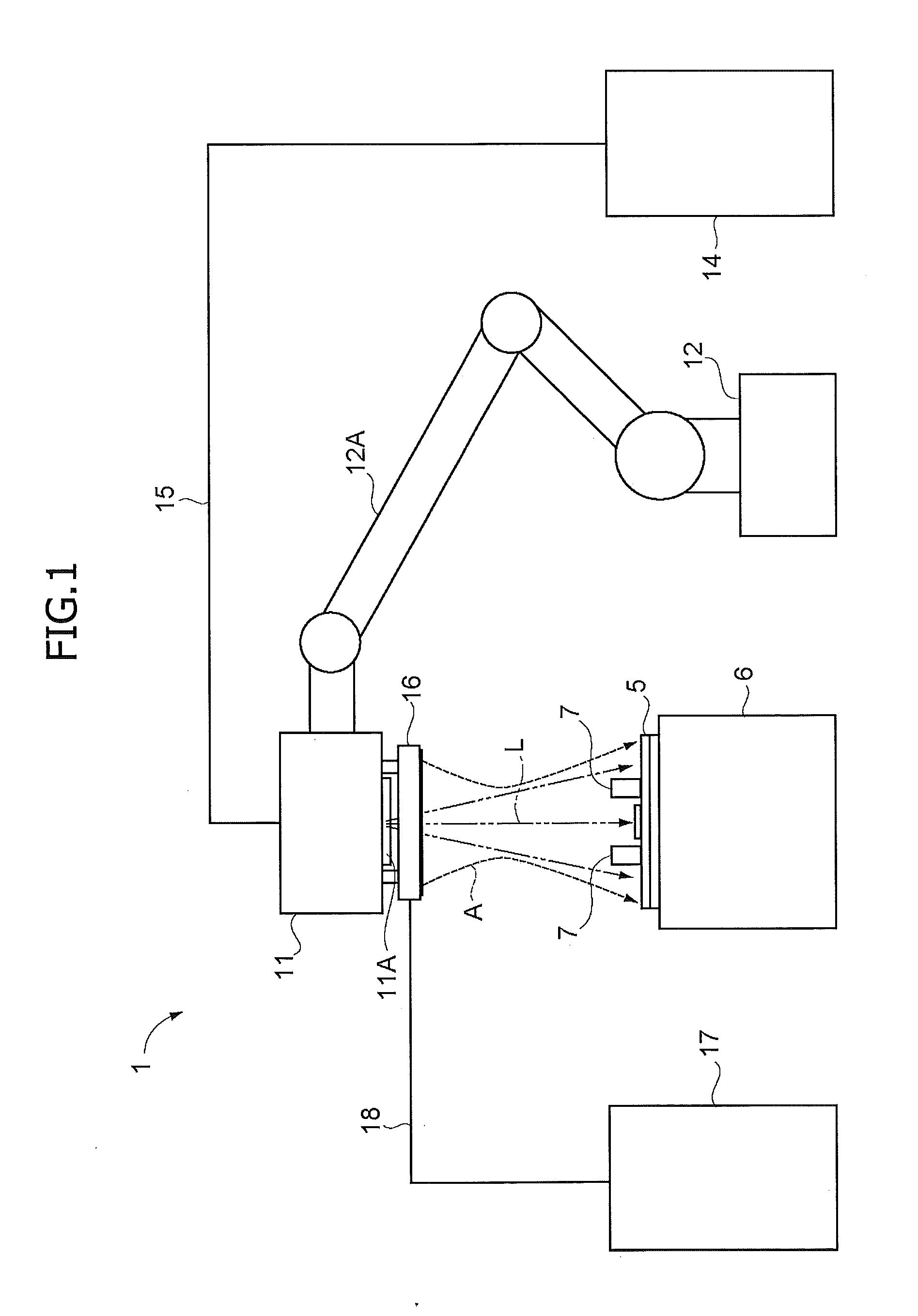
[0011]The present invention is made in view of the aforementioned problems, for example, and a first object of the present invention is to provide a laser welding apparatus which is capable of achieving high-quality welding by reliably removing a metal vapor (plume) due to irradiation of an object to be processed, such as a workpiece, with a laser beam.
[0029]According to the present invention, it is possible to reliably remove the metal vapor (plume) due to the irradiation of the object to be processed with the laser beam, and therefore, it is possible to improve the welding quality. In addition, even in a case in which the object to be processed has multiple portions to be welded at different locations, the present invention can make the welding quality uniform throughout the portions. In addition, the present invention is capable of suppressing the splattering of spatter due to irradiation of the object to be processed with the laser beam.

Problems solved by technology

This may impair the welding quality.
This may consequently cause a difference in the welding quality between the welded portions of the workpiece.
In addition, depending on how the dampers are installed, air may hit the workpiece unevenly.
For this reason, the laser welding apparatus described in U.S. Publication Application No. 2007 / 0210040 A1 may also cause a problem similar to that in a case in which the air is blown on the workpiece crosswise from the fan installed on the side of the workpiece.

Method used


Image

  • Laser welding apparatus
  • Laser welding apparatus
  • Laser welding apparatus

Examples


Embodiment Construction

[0043]The present invention now will be described more fully hereinafter in which embodiments of the invention are provided with reference to the accompanying drawings. This invention may, however, be embodied in many different forms and should not be construed as limited to the embodiments set forth herein; rather, these embodiments are provided so that this disclosure will be thorough and complete, and will fully convey the scope of the invention to those skilled in the art.

[0044]The terminology used in the description of the invention herein is for the purpose of describing particular embodiments only and is not intended to be limiting of the invention. As used in the description of the invention and the appended claims, the singular forms “a”, “an” and “the” are intended to include the plural forms as well, unless the context clearly indicates otherwise.

[0045]Unless otherwise defined, all technical and scientific terms used herein have the same meaning as commonly understood by ...


PUM

PropertyMeasurementUnit
Distanceaaaaaaaaaa

Abstract

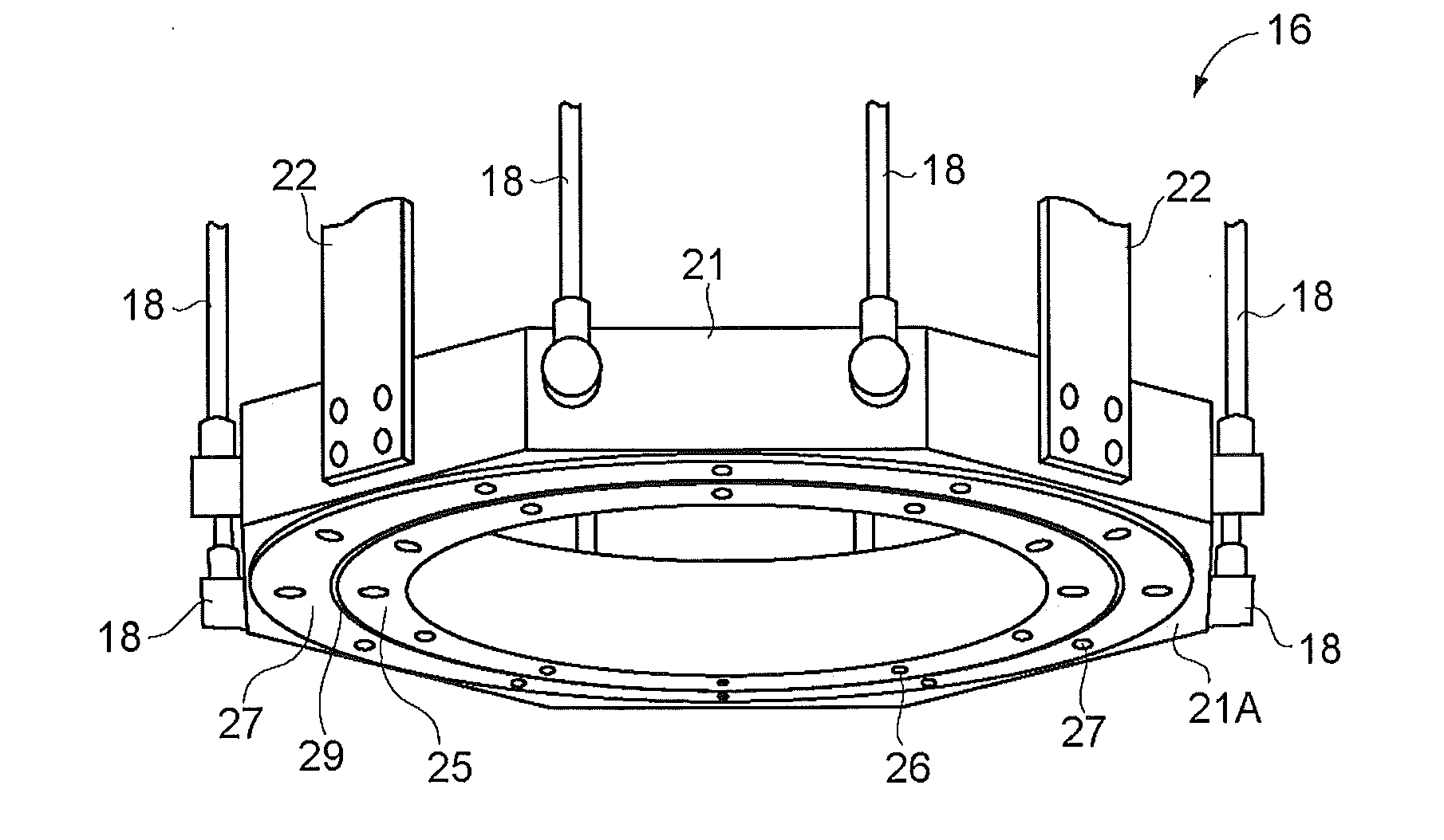
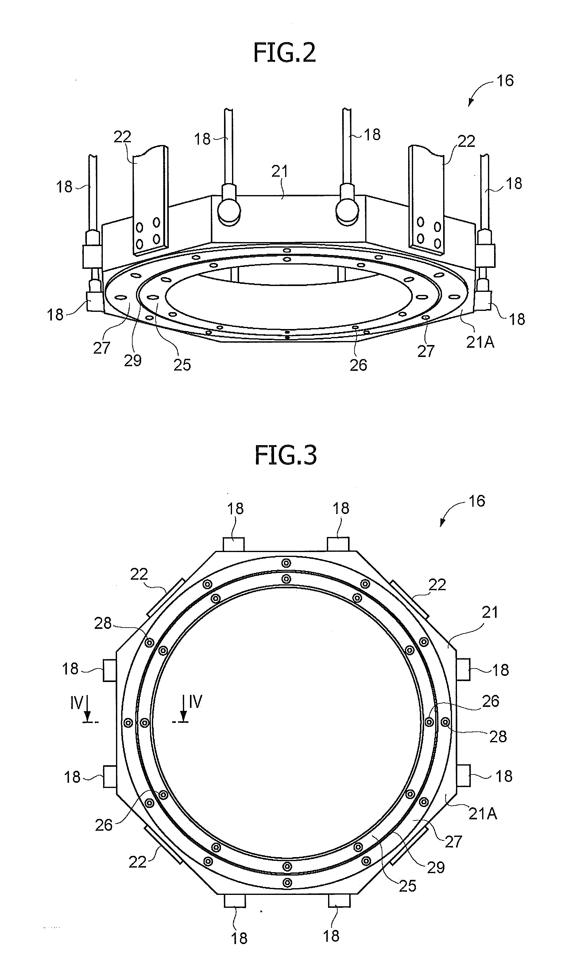
Together with a scanner device, an air blower is provided above a workpiece, and the air blower exhausts air in the shape of a ring toward the workpiece, the air in a ring shape surrounding an optical axis of a laser beam emitted from the scanner device. A housing of the air blower is formed in a ring shape, a ring-shaped cavity is formed in the housing, an inner ring member is attached to an undersurface of the housing, an outer ring member is attached to an outer peripheral side of the inner ring member, and a ring-shaped exhaust port is formed between the inner ring member and the outer ring member. An exhaust direction of the air is defined by inclination of an outer-peripheral-side end surface of the inner ring member and inclination of an inner-peripheral-side end surface of the outer ring member (FIG. 2).

Description

CROSS-RELATED APPLICATIONS[0001]This application claims priority from Japanese Patent Application No. 2010-223465; filed Oct. 1, 2010, the disclosure of which is incorporated herein by reference in its entirety.BACKGROUND OF THE INVENTION[0002]The present invention relates to a laser welding apparatus for welding by use of a laser beam.[0003]Remote laser welding has become common, in remote laser welding an object to be processes such as a workpiece is welded by remotely controlling a robot to which a laser emitting means, such as a scanner device or a laser machining head, for example, is attached. In such laser welding, a workpiece is welded by being irradiated with a laser beam from a position distant from the workpiece. Furthermore, the welding is performed on desired portions of the workpiece by remote control to move an arm of a robot or to rotate a reflecting mirror or the like provided to the laser emitting means so that different parts of the workpiece are irradiated with t...

Claims


Application Information

Patent Timeline
IPC IPC(8): B23K26/00B23K26/02B23K26/142B23K26/14B23K26/21
CPCB23K26/0807B23K26/0884B23K26/1405B23K26/14B23K26/20B23K26/12B23K26/147B23K26/142B23K26/082
Inventor KISHINO, SACHIOKOBAYASHI, MANABU
Owner SUZUKI MOTOR CORP
Learn More