
Sports Protective Garment with Impact Force Protection and Microclimate Control

Inactive Publication Date: 2012-04-05
HTFX
View PDF2 Cites 18 Cited by
  • Summary
  • Abstract
  • Description
  • Claims
  • Application Information

AI Technical Summary

Benefits of technology

[0021]An object of the invention is to provide an impact-absorbing protective garment. The garment comprises a plurality of cells of one or more sizes and shapes, each cell comprised of suitable momentarily deformable high modulus material and each cell containing its own incompressible cooling or warming material.
[0022]A further object of the invention is to provide an impact-absorbing protective garment used to protect select areas of a body, the garment comprises one or more of the following layers: (a) a middle layer comprising one or more flexible pads adapted to conform to a protected portion of the body, said layer having an inner surface adapted to face towards the body, an outer surface facing outwardly from the body, and a perimeter defining the outlines of said inner and outer surfaces; (b) an outer shell layer covering substantially all of the select area of the body being protected, adapte

Problems solved by technology

Many inadequate approaches are and have been used to produce conventional protective equipment, resulting in products that provide minimal protection against force impacts and typically provide no capacity to modify the wearer's microclimate.
Moreover, most ‘temperature controlled’ sports garments, such as the Nike® pre-cool Olympic garment, are bulky and heavy, cannot be produced to, target a given desired temperature or range of temperatures, are often restrictive of wearer movement, and provide little or no protection against and may even degrade protection from force impacts.
U.S. Pat. No. 5,530,966, the complete disclosure of which is herein incorporated by reference, discloses several sports protective garment embodiments that differentiate against then previously known art for protecting the wearer from force impact, but it does not disclose techniques for controlling microclimate.
However, these deformations and vibrations cannot occur instantaneously.
A high-velocity collision (an impact) does not provide sufficient time for these deformations and vibrations to occur.
Thus, the struck material behaves as if it were more brittle than it is, and the majority of the applied force goes into fracturing the material.
Ductile materials like steel tend to become more brittle at high loading rates, and spalling may occur on the reverse side to the impact if penetration doesn't occur.
Since most materials are weaker in tension than compression, this is the zone where cracks tend to form and grow.
To the extent that the outer shell or layer is unable to deflect a blow in the area of the impact, the energy will be transferred to the underlying material in a more localized manner, resulting in a high force per unit of area that is likely to cause greater injury than if the force were more distributed.
This said, it should be recognized that materials capable of providing impact protection at certain speeds generally provide inadequate protection at other speeds.
For example, rigid or non-resilient materials may be effective at protecting the wearer at high impact speeds but are almost wholly ineffective at absorbing the impact energy of low speed impacts.
None of this, however, considers the integration of effective microclimate control into the sports protective garment.
Heretofore, it has not been possible to integrate both state of the art force impact protection and state of the art microclimate control in a light garment that still affords necessary flexibility and range of motion.
Unfortunately, previous efforts to create garments that modify wearer microclimate suffer from profound disadvantages when used in sporting applications, including: adding too much weight to the wearer (which detracts from physical achievement or results), overly restricting the wearer's range of motion, requiring proximal connection to ancillary systems—to enable recirculation, for instance and creating a sub-optimal microclimate temperature and thermal consistency when viewed from the perspective of either ambient temperature or what is considered safe for long-term use in close proximity to the body.
It is well documented, for instance, that overly cold temperatures, such as can be created by ice or gels, cause vasoconstriction and reduced capillary flow—which ultimately overcomes the body's own internal cooling systems and can lead to dangerous overheating.
Beyond these significant thermal challenges, heretofore, the incorporation of available cooling or warming systems into sports protective garments has degraded the garment's force impact capabilities.
Liquid-gas phase changes are not practical for use as thermal storage due to the large volumes or high pressures required to store the materials when in their gas phase.
Solid-solid phase changes are typically very slow and have a rather low heat of transformation.
Certain properties of water / ice, however, may render it of little use (or useless) in given applications, including: the phase temperature cannot be modified (ice is too cold for extended use in most biological cooling applications, for instance, as applying ice to tissue quickly results in vasoconstriction and vastly reduced capillary blood flow—often resulting in skin or tissue damage), the water to ice transition results in a volumetric expansion of ˜9%—making it a challenge to use in mechanical applications, and ice exhibits little mechanical “give” in the fully frozen state.
While this expansion isn't particularly relevant in most sports protective garment applications, the overly cold temperature is.
Others lose the capacity to transition sharply after a certain number of uses (eutectics often degrade after a few thousand cycles, rendering them of little use in most applications).
Because some are caustic they have to be encapsulated in inert materials, reducing their effective energy storage capacity for a given volume of PCM.

Method used


Image

  • Sports Protective Garment with Impact Force Protection and Microclimate Control
  • Sports Protective Garment with Impact Force Protection and Microclimate Control
  • Sports Protective Garment with Impact Force Protection and Microclimate Control

Examples


Embodiment Construction

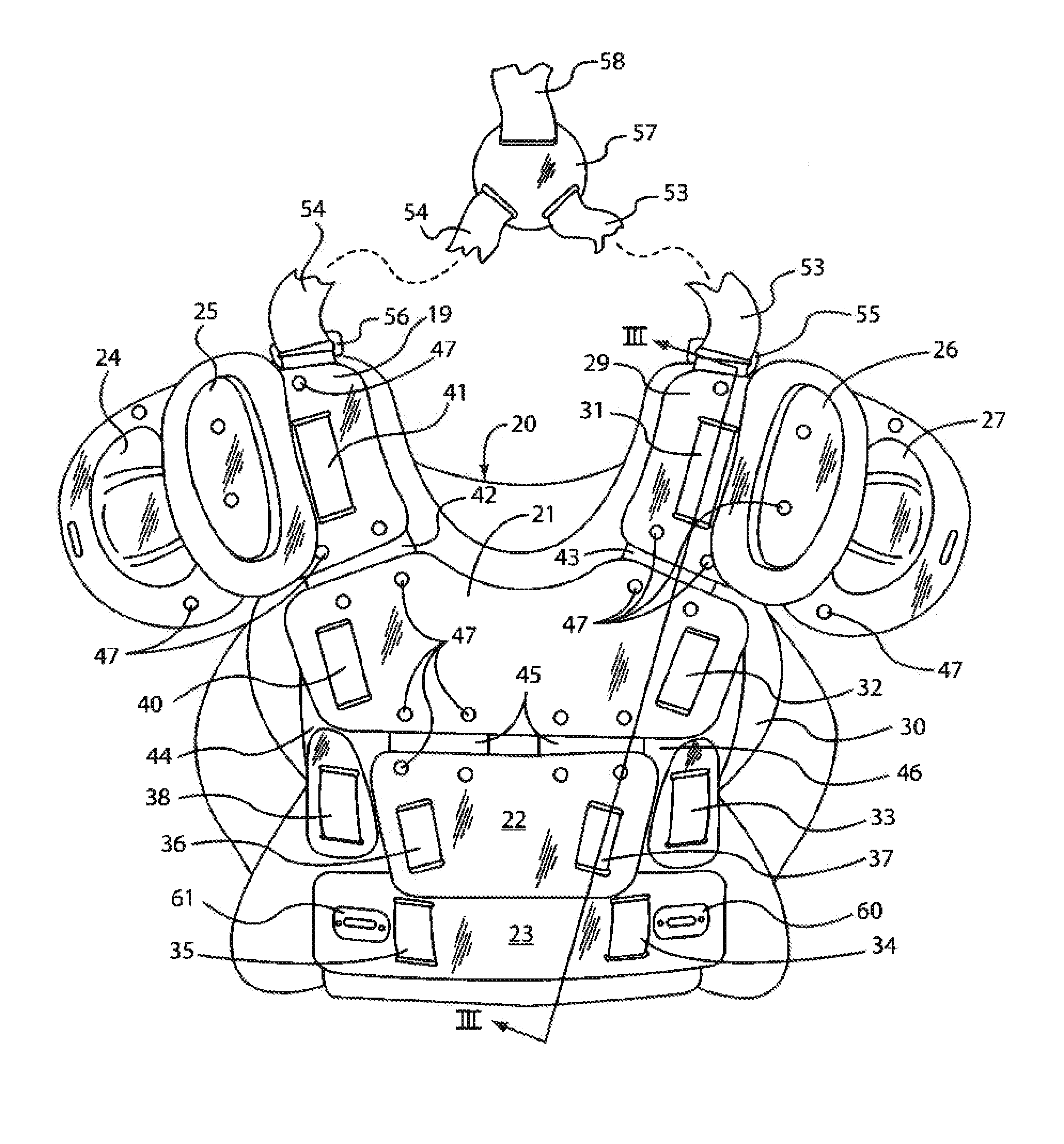
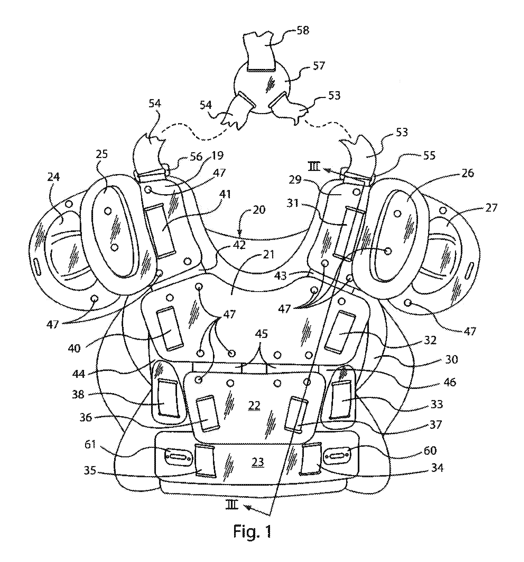
[0034]Referring to the drawings now in detail, reference is first made to FIG. 1, wherein a protective garment in the form of an umpire's vest is shown, generally designated by the numeral 20.

[0035]The vest 20 has an outer shell layer comprised of a plurality of plate elements that cover substantially the entire frontal area of the upper torso. The plate elements include a breastplate element 21, a solar element 22, and abdominal element 23, and shoulder elements 19, 24, 25, 26, 27 and 29. All of the elements are mounted to a middle layer 30 by anchor straps 31, 32, 33, 34, 35, 36, 37, 38, 40 and 41 that are hook and loop strips of the “VELCRO” type which fasten the various plate elements of the outer shell layer to the middle layer 30. The various plate elements are interconnected by flexible connectors 42, 43, 44, 45 and 46 to which the plates are attached by means of rivets 47.

[0036]As illustrated in FIG. 2, the plates 19, 24 and 25 are connected flexible connectors 48, 50, and t...


PUM


Abstract

An impact absorbing protective garment is provided, for wearing about the torso of a body, such as a baseball umpire, that comprises three layers. There is an outer shell layer comprised of a plurality of plate elements that are generally stiff, shock-resistant lightweight material, that are fastened to a middle layer. The middle layer is in the form of a flexible pad having various components, and that provides an intermediate thickness of cushioning material inside the outer shell layer. There is an inner layer carried by the middle layer that comprises a plurality of cells of phase change material, with the various cells being separated from each other by sealing zones. Upon sufficient impact the individual cells can communicate through small pores in the sealing zones or when the sealing zones rupture under impact pressure, to assist in impact absorption. The inner layer, in its cells, contains a phase change material that is a means for effecting a relatively constant microclimate cooling or heating of the area of the torso of the body which it confronts.

Description

CROSS-REFERENCE TO RELATED APPLICATIONS[0001]This application claims priority from U.S. provisional application No. 61 / 320,867 filed Apr. 5, 2010, the complete disclosure of which is herein incorporated by reference.BACKGROUND OF THE INVENTION[0002]As is already known in the art, protective garments for athletes are specifically designed to accommodate the hazards of a particular sport or activity. For example, football pads are designed to protect against body impacts while permitting the player to perform the maneuvers required on the football field. Lacrosse pads are designed to protect against limited body impact but also against impact from lacrosse sticks and balls, while allowing the athlete to perform the maneuvers required by the game. In many cases, the padding may be specifically designed for a particular playing position, with overall pad design different for players at different positions. In football, the protective needs of quarterbacks are different from those of rec...

Claims


Application Information

Patent Timeline
IPC IPC(8): A41D13/015
CPCA41D13/0055A41D13/0518A41D13/015
Inventor DOHERTY, BRIANMCCALL, ERBY J.MCMORRIS, III, JOHN A.
Owner HTFX
Learn More