
Windmill Generator with Mechanically Tuneable Permanent Magnetic Field

a permanent magnetic field, windmill generator technology, applied in the direction of electric generator control, magnetic circuit shape/form/construction, magnetic circuit rotating parts, etc., can solve the problem that many known alternator applications cannot control the rpm of the alternator, and achieve the effect of improving the starting torque and high rpm efficiency

Inactive Publication Date: 2012-03-29
MOTOR GENERATOR TECH INC
View PDF0 Cites 17 Cited by
  • Summary
  • Abstract
  • Description
  • Claims
  • Application Information

AI Technical Summary

Benefits of technology

[0007]In accordance with one aspect of the present invention, there are provided apparatus and methods to vary the flux strength of rotor / armature in an electric motor to provide improved starting torque and high RPM efficiency.
[0008]In accordance with another aspect of the present invention, there are provided apparatus and methods to vary the magnetic flux strength of rotor / armature in generator / alternator applications to control output voltage independent of RPM. Many known alternator applications cannot control alternator RPM, for example, automotive alternators which must operate at an RPM proportional to engine RPM and wind power generation which are subject to wind speed. Varying the magnetic flux strength of rotor / armature allows output voltage to be controlled independently of RPM thereby eliminating the need for an inverter or separate electromagnetic exciter coil.
[0011]In accordance with still another aspect of the present invention, there are provided apparatus and methods adaptable to vary the magnetic field of a motor suitable for application to an induction motor to provide a weak magnetic field for starting the motor in an asynchronous mode and to provide a strong magnetic field for efficient operation in a synchronous mode.

Problems solved by technology

Many known alternator applications cannot control alternator RPM, for example, automotive alternators which must operate at an RPM proportional to engine RPM and wind power generation which are subject to wind speed.

Method used


Image

  • Windmill Generator with Mechanically Tuneable Permanent Magnetic Field
  • Windmill Generator with Mechanically Tuneable Permanent Magnetic Field
  • Windmill Generator with Mechanically Tuneable Permanent Magnetic Field

Examples


first embodiment

[0085]A side view of apparatus 40a for adjusting the cylindrical two pole permanent magnets 16 in a first magnet position is shown in FIG. 19A, an end view of the apparatus 40a for adjusting the cylindrical two pole permanent magnets in the first magnet position is shown in FIG. 19B, a side view of the apparatus 40a for adjusting the cylindrical two pole permanent magnets 16 in a second magnet position is shown in FIG. 20A, and an end view of the apparatus 40a for adjusting the cylindrical two pole permanent magnets in the second magnet position is shown in FIG. 20B. The apparatus for adjusting 40a includes a linear motor 42 which is preferably a stepper motor, a shaft 48 actuated axially by the linear motor 42, and ring 46 axially actuated by the shaft 48, and an arm (or arms) 44 actuated by the ring 46 and connected to one of six toothed racks 52. The toothed racks 52 engaged gears 50 attached to the magnets 16 to rotate the magnets 16. Actuation of the shaft 48 to the right pulls...

second embodiment

[0086]A side view of apparatus 40b for adjusting the cylindrical two pole permanent magnets 16 in a first magnet position is shown in FIG. 21A, an end view of the apparatus 40b for adjusting the cylindrical two pole permanent magnets in the first magnet position is shown in FIG. 21B, a side view of the apparatus 40b for adjusting the cylindrical two pole permanent magnets 16 in a second magnet position is shown in FIG. 22A, and an end view of the apparatus 40b for adjusting the cylindrical two pole permanent magnets in the second magnet position is shown in FIG. 22B. The apparatus for adjusting 40b includes the linear motor 42 which is preferably a stepper motor, a shaft 48 actuated axially by the linear motor 42, and ring 46 axially actuated by the shaft 48, and a bent elbow 45 actuated by the ring 46 and connected to one of six toothed racks 52. The bent elbow 45 is biased to a bent position, for example, with a 90 degree bend. When the ring 46 moves to the right to release the be...

third embodiment

[0087]A side view of apparatus 40c for adjusting the cylindrical two pole permanent magnets 16 in a first magnet position is shown in FIG. 23A, an end view of the apparatus 40c for adjusting the cylindrical two pole permanent magnets in the first magnet position is shown in FIG. 23B, a side view of the apparatus 40c for adjusting the cylindrical two pole permanent magnets 16 in a second magnet position is shown in FIG. 24A, and an end view of the apparatus 40c for adjusting the cylindrical two pole permanent magnets in the second magnet position is shown in FIG. 24B. The apparatus for adjusting 40c includes the linear motor 42 which is preferably a stepper motor, a shaft 48 actuated axially by the linear motor 42, a first piston 47 connected to the shaft 48 and a second piston 49 in fluid communication with the piston 47 and connected to one of the six toothed racks 52. When the piston 47 moves to the right the second piston 49 is drawn radially in and the toothed rack 52 is pulled ...


PUM


Abstract

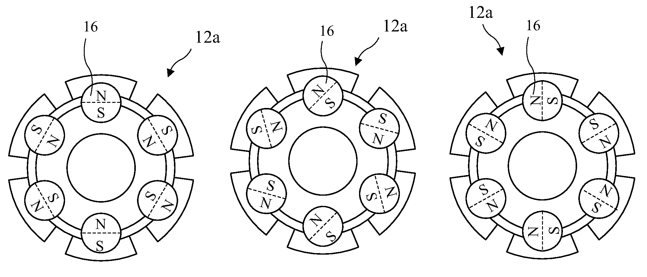
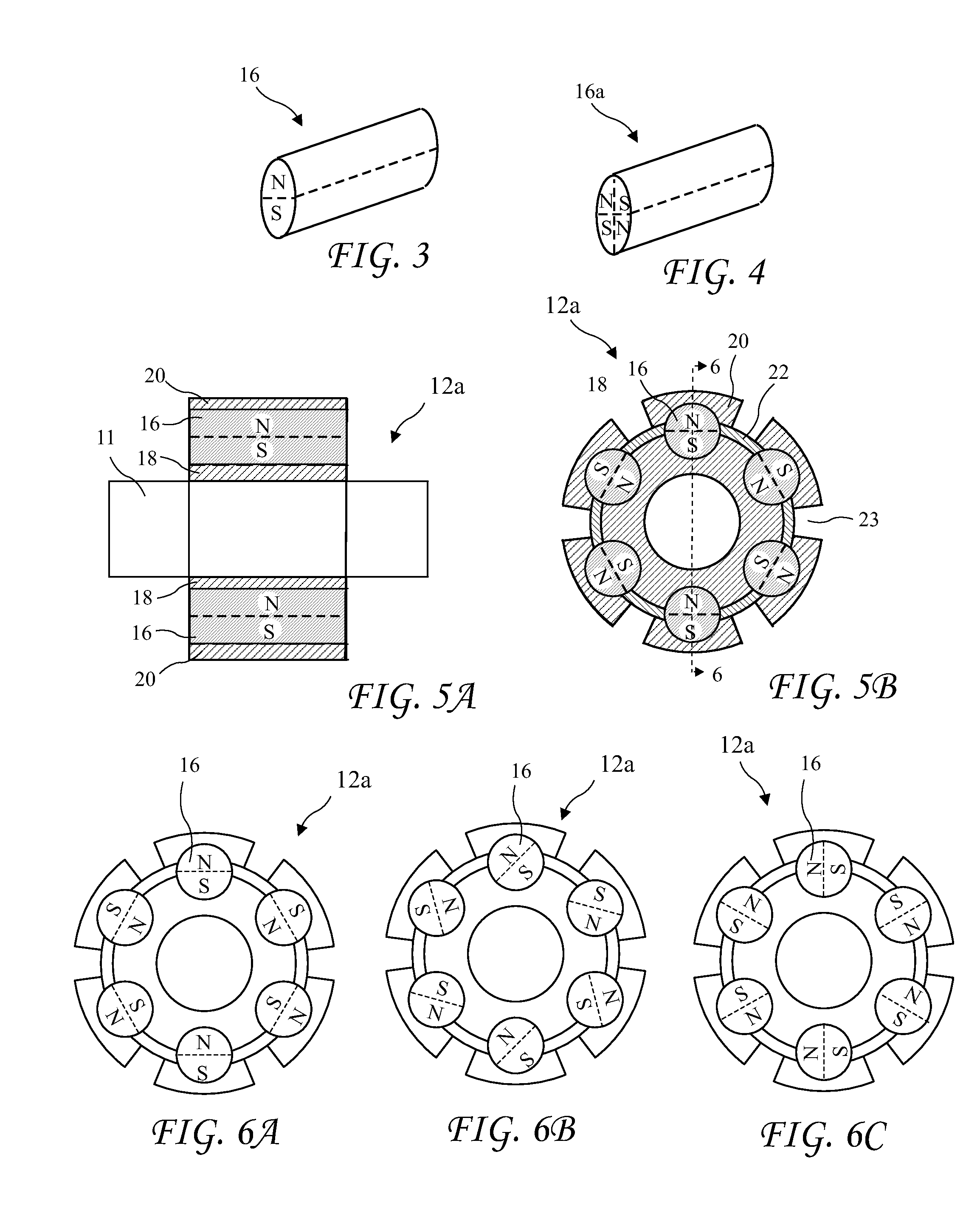
Apparatus and method for tuning the magnetic field of windmill generators to obtain efficient operation over a broad RPM range. The windmill generator includes fixed windings (or stator) inside a rotating rotor carrying permanent magnets. The permanent magnets are generally cylindrical and have North and South poles formed longitudinally in the magnets. Magnetically conducting circuits are formed by the magnets residing in magnetic conducting pole pieces (for example, low carbon or soft steel, and / or laminated insulated layers, of non-magnetizable material). Rotating the permanent magnets, or rotating non-magnetically conducting shunting pieces, inside the pole pieces, either strengthens or weakens the resulting magnetic field to adjust the windmill generators for low RPM torque or for efficient high RPM efficiency. Varying the rotor magnetic field adjusts the voltage output of the windmill generators allowing the windmill generator to maintain a fixed voltage output.

Description

[0001]The present application is a Continuation In Part of U.S. patent application Ser. No. 12 / 610,271 filed Oct. 30, 2009, and of U.S. patent application Ser. No. 12 / 905,834 filed Oct. 15, 2010, which applications are incorporated in their entirety herein by reference.BACKGROUND OF THE INVENTION[0002]The present invention relates to electric motors and generators and in particular to adjusting the orientation of fixed magnets and / or non-magnetically conducting shunting piece in a rotor to obtain efficient operation at various RPM.[0003]Brushless DC motors are often required to operate at various RPM but can only achieve efficient operation over a limited RPM range. Further, generators and alternators are often required to operate over a broad RPM range. For example, automotive alternators operate at an RPM proportional to engine RPM and windmill alternators operate at an RPM proportional to wind speed. Unfortunately, known alternators generate electricity at a voltage proportion to...

Claims


Application Information

Patent Timeline
Patent Type & Authority Applications(United States)
IPC IPC(8): H02P9/40H02P9/48H02K1/28
CPCH02K1/276H02K7/1838H02P9/48H02P9/40H02K21/028H02K21/029
Inventor FINKLE, LOUIS J.
Owner MOTOR GENERATOR TECH INC
Learn More