
Stacking System For Intermodal Platforms

a technology of intermodal platforms and stacking systems, which is applied in the direction of containers, transportation items, tray containers, etc., can solve the problems of inefficiency of moving empty intermodal containers, cost nearly as much to haul an empty container as a full one, and the inability of rail well cars to move two standard intermodal containers at once, so as to reduce the risk of operator injury or damage to the components, and reduce the risk of operator injury or damag

Active Publication Date: 2012-03-29
PILLAR CAPITAL CORP
View PDF0 Cites 15 Cited by
  • Summary
  • Abstract
  • Description
  • Claims
  • Application Information

AI Technical Summary

Benefits of technology

"The present invention provides a collapsible transport platform that overcomes the limitations of prior art. The platform has arcuate beams that provide superior load properties, allowing for heavier loads while minimizing overall weight. The platform can accommodate heavier loads while minimizing operator injury or damage to components. The platform can be stacked together or with standard intermodal containers, and it provides a standard fitment for connection with other containers while still allowing for full-width loading and hauling of cargo. The platform is safer, quicker to operate, and has a higher haul capacity than those in the prior art. The amount of human involvement in the mechanical operation of the platform is considerably minimized."

Problems solved by technology

However, the inevitable need to relocate empty intermodal containers is not efficient, because the containers take up as much space empty as they do full.
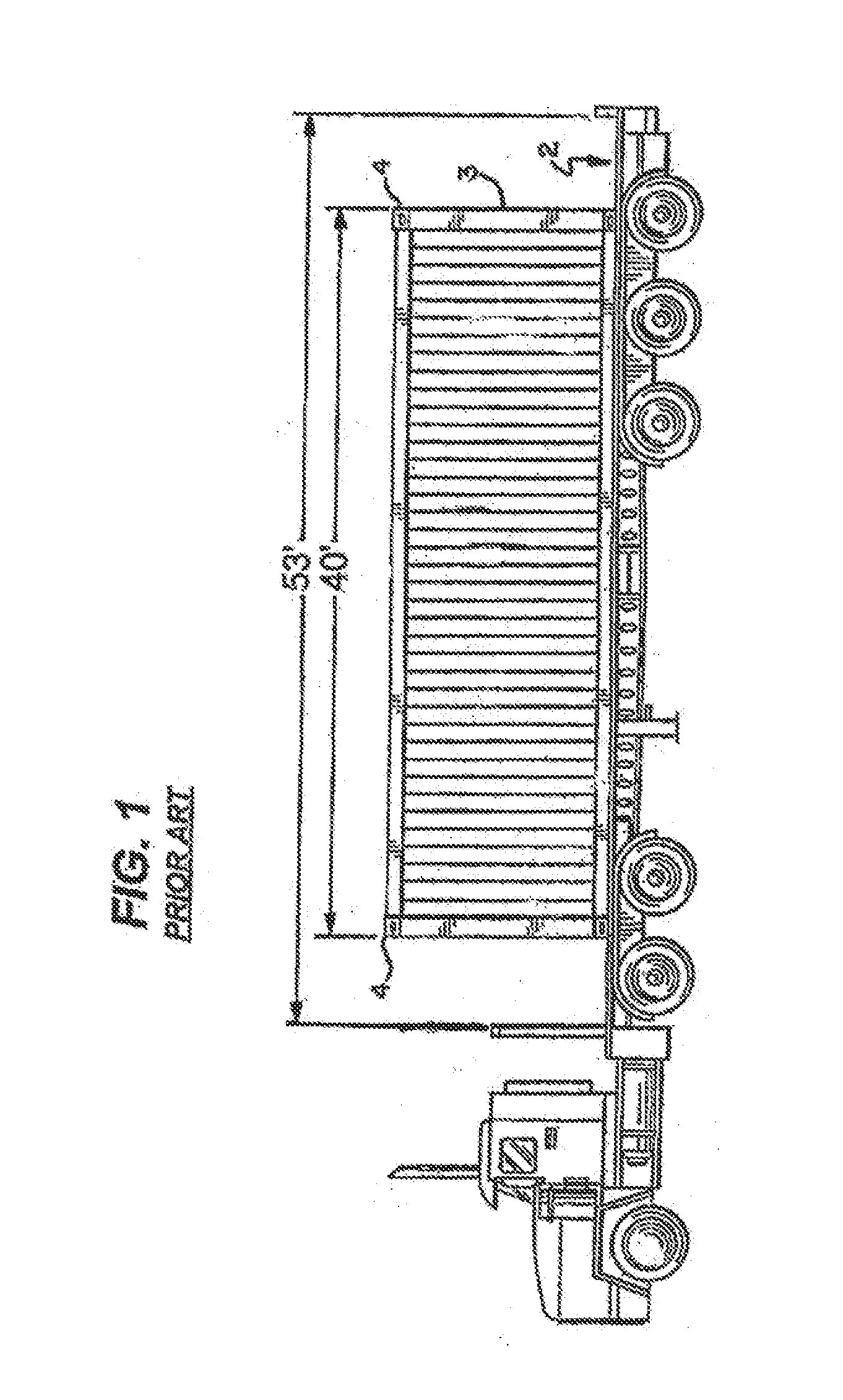
Even when empty, each container usually requires its own trailer chassis for highway transport, because just two standard containers stacked together would be too high for truck transport.
At most, rail well cars can only move two standard intermodal containers at once, regardless of whether they are full or empty.
Thus, it costs nearly as much to haul an empty container as a full one, but without the revenue from the transport of cargo to offset the cost.
Even if container relocation is unnecessary, the empty containers still present a disadvantage in that they take up just as much space when stored in a yard as do full containers.
Not only is this a slow process that presents spatial constraints to the forklift operator, it does not allow for the loading of lengthy materials such as pre-formed steel beams, lumber, or other materials not suitable for palletizing.
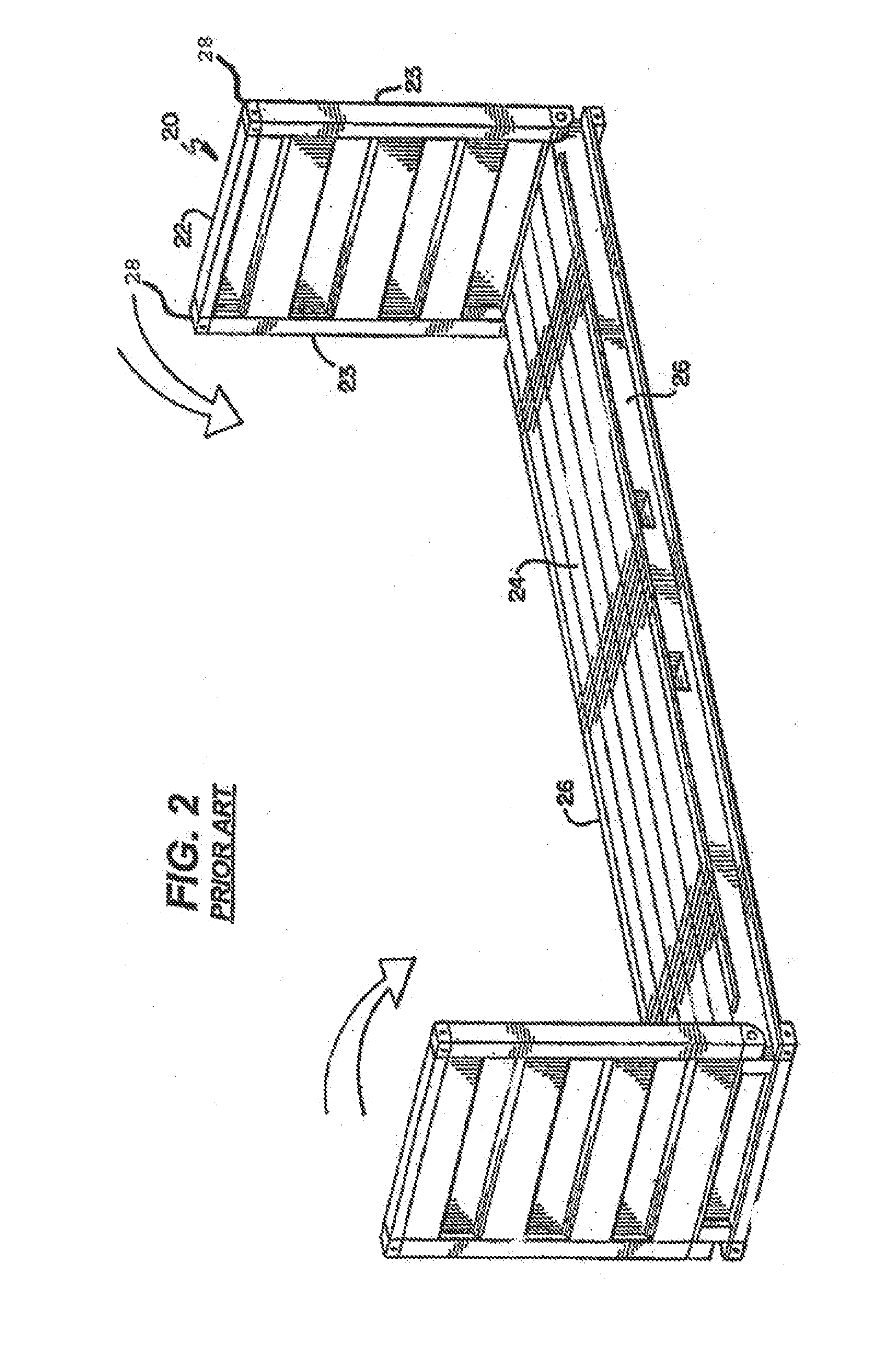
However, flatbeds are not used for intermodal transport because they cannot be stacked when loaded, and do not provide the requisite structural fitments at the Forty Foot Points for lifting by an overhead crane.
Though such designs have been attempted, they have not been adopted due to issues with safety, durability and functionality.
Though springs and counterweights have been used to assist with manual manipulation, the high level of operator involvement lends to safety hazards and is very time consuming.
Moreover, the necessity of structural fitments at the Forty Foot Points conflicts with the desire to enable side and / or top loading of large materials.
This is preferably done without enabling components to extend laterally beyond the side envelope of the flatbed, as this could cause a safety hazard in transit should a component come unpinned.
Prior art collapsible intermodal designs have been functionally limited to forty-five feet of usable deck length.
Finally, prior art attempts at intermodal flatbeds have been limited in the amount of load they can support during lifting operations.
This point loading can lead to deformation of the flatbed if it is not sufficiently strong.
Though the flatbed can be made stronger by adding more steel, this adds weight to the empty load.

Method used


Image

  • Stacking System For Intermodal Platforms
  • Stacking System For Intermodal Platforms
  • Stacking System For Intermodal Platforms

Examples


Embodiment Construction

[0054]The description that follows describes, illustrates and exemplifies one or more particular embodiments of the present invention in accordance with its principles. This description is not provided to limit the invention to the embodiments described herein, but rather to explain and teach the principles of the invention in such a way to enable one of ordinary skill in the art to understand these principles and, with that understanding, be able to apply them to practice not only the embodiments described herein, but also other embodiments that may come to mind in accordance with these principles. The scope of the present invention is intended to cover all such embodiments that may fall within the scope of the appended claims, either literally or under the doctrine of equivalents.

[0055]It should be noted that in the description and drawings, like or substantially similar elements may be labeled with the same reference numerals. However, sometimes these elements may be labeled with...


PUM


Abstract

A stacking and lifting system for intermodal transport platforms is disclosed. Transport platforms can be converted between a storage or empty transport position and a haul or load position through rotation of support posts that provide structural support and locate fitments that align with adjoining fitments on standard intermodal containers. The support posts have fitments at their distal ends for use during lifting or stacking operations when the transport platform is loaded and in use. The support posts also have stacking blocks that provide flip-up fitments for use when the posts are in a lowered configuration for stacking transport platforms with other transport platforms or with standard intermodal containers. The stacking blocks may be lifted directly or may be locked in to adjoining fitment housings, such that the transport platform will cling to the adjoining platform or intermodal container above it that is being lifted.

Description

CROSS-REFERENCE TO RELATED APPLICATION[0001]This application is a non-provisional patent application of and claims priority to U.S. Provisional Patent Application No. 61 / 387,905, filed on Sep. 29, 2010, entitled “COLLAPSIBLE INTERMODAL FLATBED AND METHOD OF USE”, and is a non-provisional patent application of and claims priority to U.S. Provisional Patent Application No. 61 / 433,198, filed on Jan. 14, 2011, entitled “COLLAPSIBLE INTERMODAL TRANSPORT PLATFORM,” and is a non-provisional patent application of and claims priority to U.S. Patent Application Ser. No. 61 / 440,803, filed on Feb. 8, 2011, entitled “COLLAPSIBLE INTERMODAL TRANSPORT PLATFORM.” Each of these applications are incorporated herein by reference in their entirety.TECHNICAL FIELD[0002]The present invention relates to equipment for transporting cargo, and methods for operating such equipment. More specifically, the invention is directed at equipment for facilitating the storage and relocation of multiple, full-width shi...

Claims


Application Information

Patent Timeline
Patent Type & Authority Applications(United States)
IPC IPC(8): B65D19/00
CPCB61D47/00B65D88/022B65D88/129Y02T30/30B65D90/0033B60P7/135B65D19/12B65D88/522Y02T30/00B60P1/64B61D45/00B65D88/12
Inventor CRANE, MURRAY
Owner PILLAR CAPITAL CORP
Learn More