Composite antenna and portable telephone
a portable telephone and antenna technology, applied in the field of mobile phones, can solve the problems of reducing the chances of the user's hand coming to simultaneously cover both the main antenna and the auxiliary antenna, and deteriorating the reception conditions, and achieve the effect of greater miniaturization
- Summary
- Abstract
- Description
- Claims
- Application Information
AI Technical Summary
Benefits of technology
Problems solved by technology
Method used
Image
Examples
embodiment 1
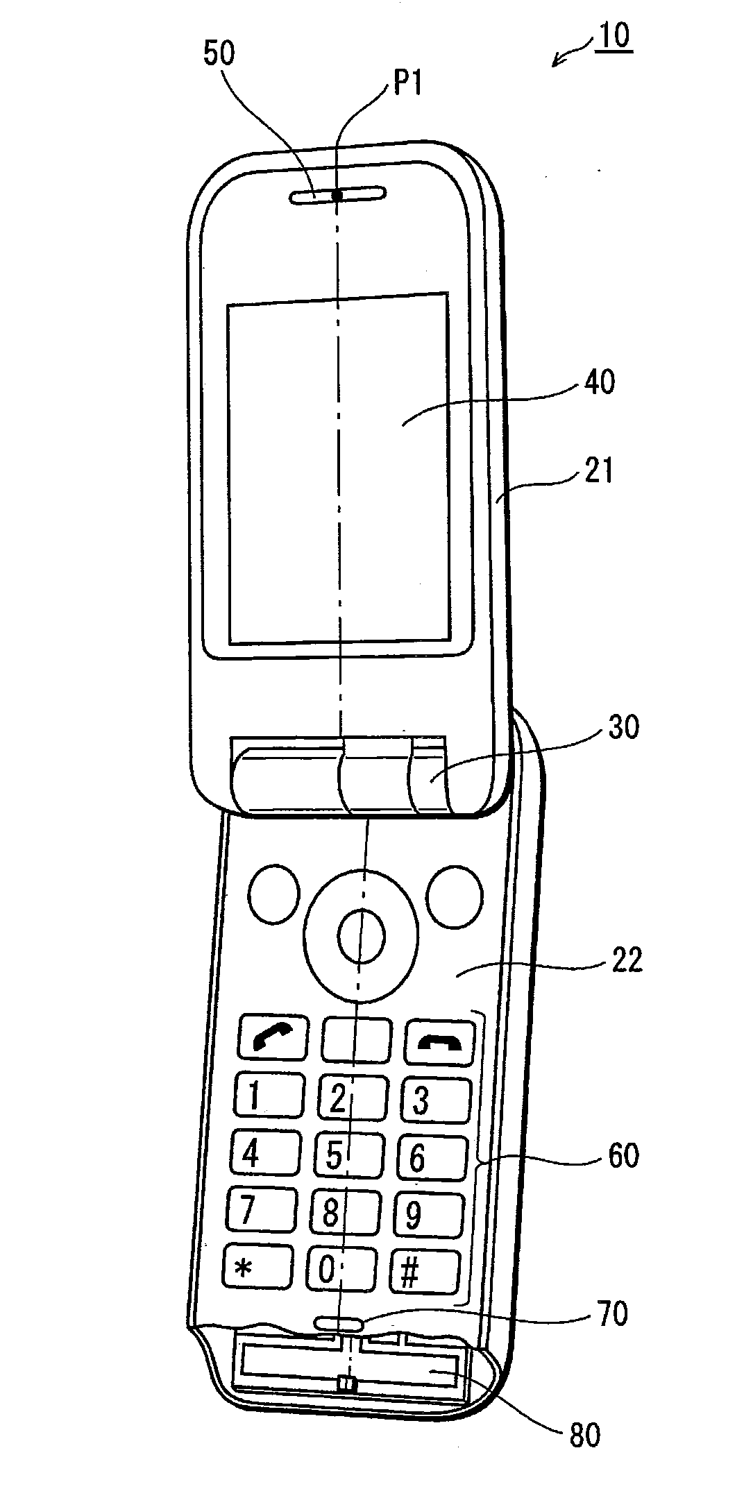
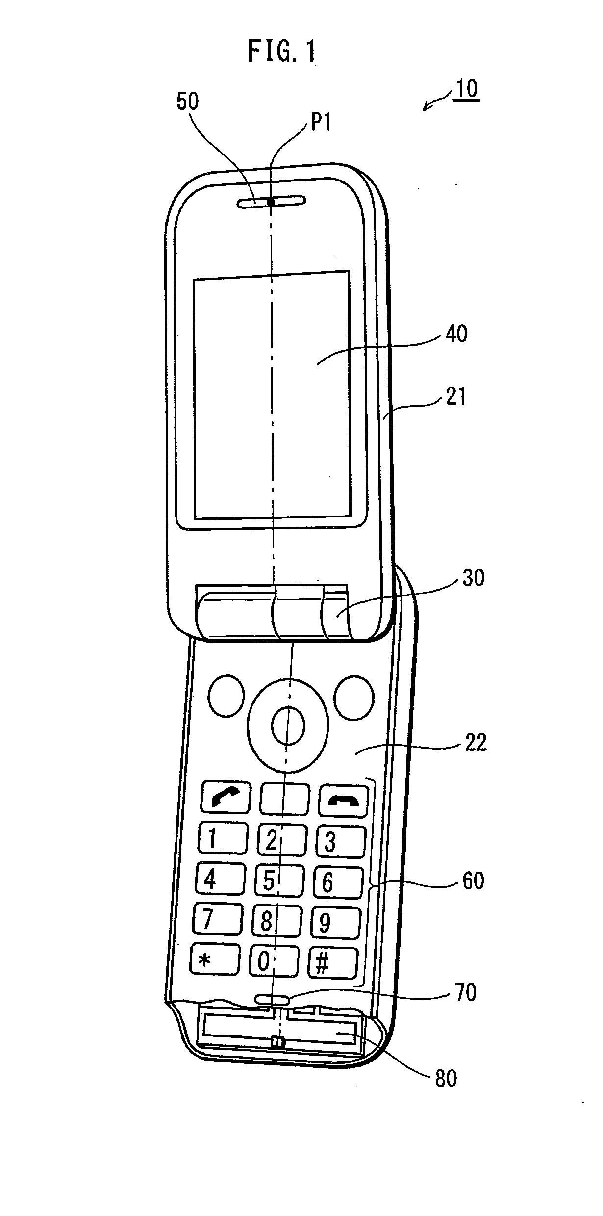
[0019]FIG. 1 is a perspective diagram of a mobile phone 10 pertaining to Embodiment 1 of the present invention. The mobile phone 10 is a clamshell phone made up of a first casing 21 and a second casing 22 connected via a hinge 30 so as to enable opening and closing. FIG. 1 illustrates a particular instance in which the first casing 21 and the second casing 22 are open. Ordinarily, when the mobile phone 10 is used for a call, the first casing 21 and the second casing 22 remain open, as shown in FIG. 1.
[0020]The first casing 21 includes a display unit 40 and an earphone unit 50, embedded therein. The display unit 40 is a liquid crystal display. As shown in FIG. 1, the screen of the display unit 40 is provided on the surface of the first casing 21 and is exposed when the first casing 21 and the second casing 22 are open. The earphone unit 50 includes a speaker. When the mobile phone 10 is used for a call, the speaker reproduces sounds produced by the other party in the conversation. Th...
embodiment 2
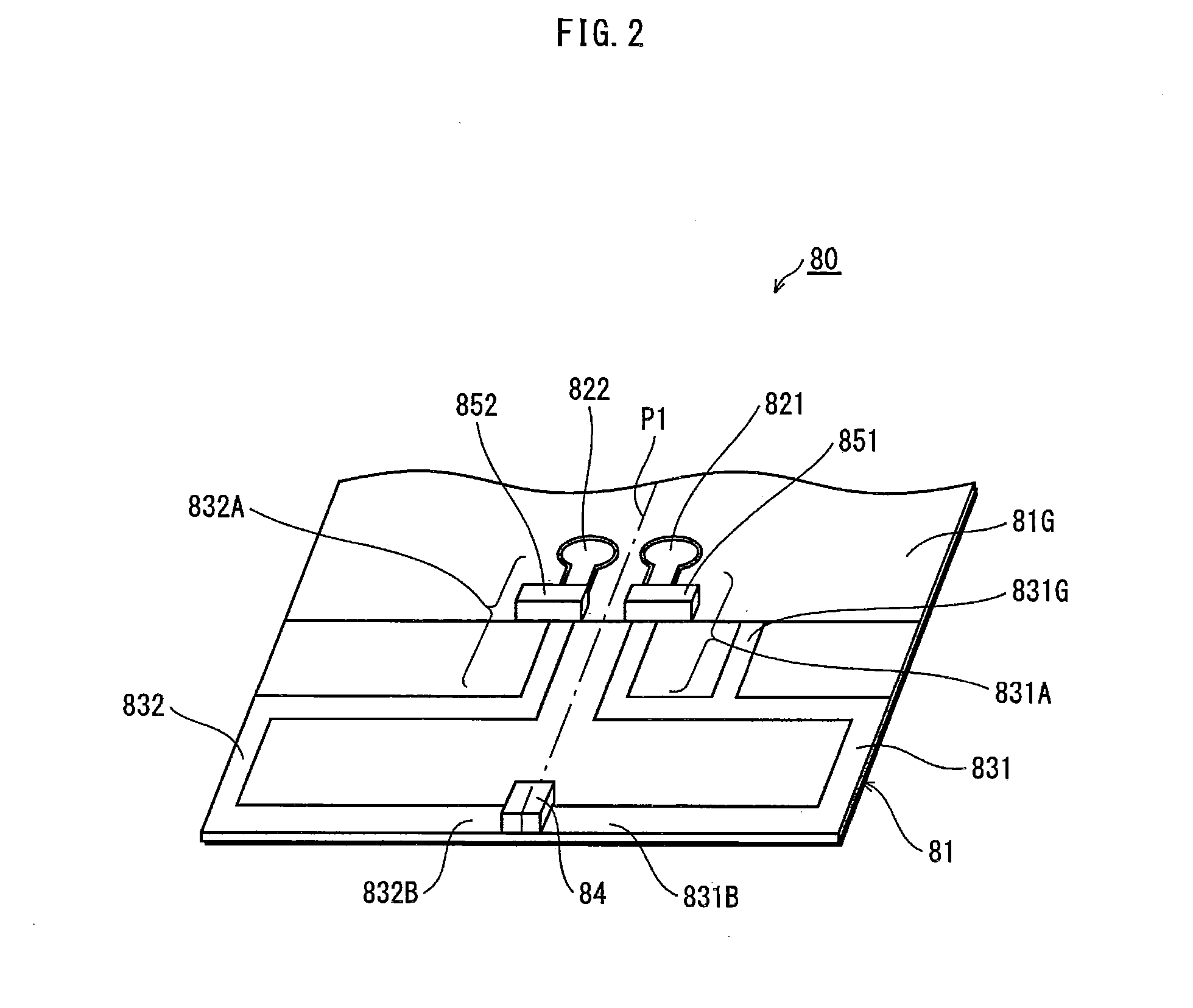
[0052]FIG. 5 is an equivalent circuit diagram of the complex antenna 80A pertaining to Embodiment 2 of the present invention. The complex antenna 80A differs from the complex antenna 80 shown in FIG. 3 in the inclusion of a series resonant circuit 84A. Aside from this point, the complex antenna 80A pertaining to Embodiment 2 is identical to the above-described complex antenna 80 pertaining to Embodiment 1. That is, the complex antenna 80A shown in FIG. 5 is, like the complex antenna 80 shown in FIG. 2, disposed within the second casing 22 of the mobile phone 10 from FIG. 1, being particularly concentrated in the vicinity of the mouthpiece unit 70. Furthermore, the structure of the complex antenna 80A shown in FIG. 5 as implemented on the substrate is identical to that of the complex antenna 80 shown in FIG. 2. Accordingly, FIG. 5 uses the same reference numbers as FIGS. 1, 2, and 3 to refer to components identical to those of the complex antenna 80 pertaining to Embodiment 1. Furthe...
embodiment 3
[0058]FIG. 6 is a perspective diagram of a complex antenna 80B pertaining to Embodiment 3 of the present invention. FIG. 7 is an equivalent circuit diagram of the complex antenna 80B. The complex antenna 80B has a second antenna element 832 that differs from that of the complex antenna 80 shown in FIGS. 2 and 3. Aside from this point, the complex antenna 80B pertaining to Embodiment 3 is identical to the above-described complex antenna 80 pertaining to Embodiment 1. That is, the complex antenna 80B shown in FIG. 6 is, like the complex antenna 80 shown in FIG. 2, disposed within the second casing 22 of the mobile phone 10 from FIG. 1 and particularly concentrated in the vicinity of the mouthpiece unit 70. Furthermore, the complex antenna 80B shown in FIG. 6 includes elements identical to the complex antenna 80 shown in FIG. 2. Accordingly, FIGS. 6 and 7 use the same reference numbers as FIGS. 1, 2, and 3 to refer to components identical to those of the complex antenna 80 pertaining t...
PUM
 Abstract
Description
Claims
Application Information
 - R&D
- Intellectual Property
- Life Sciences
- Materials
- Tech Scout
- Unparalleled Data Quality
- Higher Quality Content
- 60% Fewer Hallucinations
Browse by: Latest US Patents, China's latest patents, Technical Efficacy Thesaurus, Application Domain, Technology Topic, Popular Technical Reports.
© 2025 PatSnap. All rights reserved.Legal|Privacy policy|Modern Slavery Act Transparency Statement|Sitemap|About US| Contact US: help@patsnap.com


