
Electrical Submersible Pump System Having High Temperature Slot, End Bell and Phase-to-Phase Insulation

a submersible pump and high temperature technology, applied in the direction of coupling device connection, magnetic circuit shape/form/construction, borehole/well accessories, etc., can solve the problems of motor overheating and motor life reduction

Active Publication Date: 2012-03-15
BAKER HUGHES INC
View PDF5 Cites 19 Cited by
  • Summary
  • Abstract
  • Description
  • Claims
  • Application Information

AI Technical Summary

Problems solved by technology

In spite of the heat transfer between the fluid and the motor, over a period of time the motor may become overheated.
Overheating may a problem when the fluid has a high viscosity, a low specific heat, and a low thermal conductivity.
Elevated well temperatures can reduce motor life.

Method used


Image

  • Electrical Submersible Pump System Having High Temperature Slot, End Bell and Phase-to-Phase Insulation
  • Electrical Submersible Pump System Having High Temperature Slot, End Bell and Phase-to-Phase Insulation
  • Electrical Submersible Pump System Having High Temperature Slot, End Bell and Phase-to-Phase Insulation

Examples


Embodiment Construction

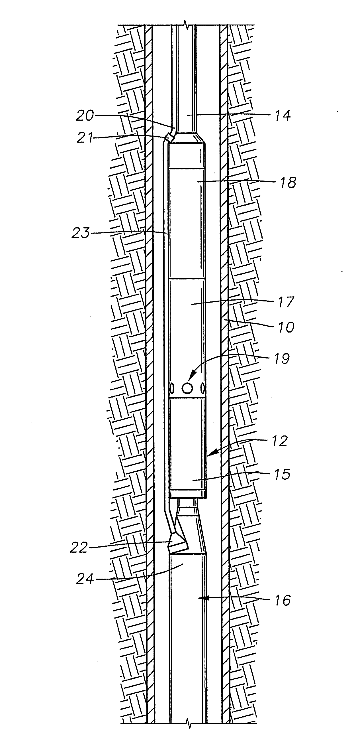
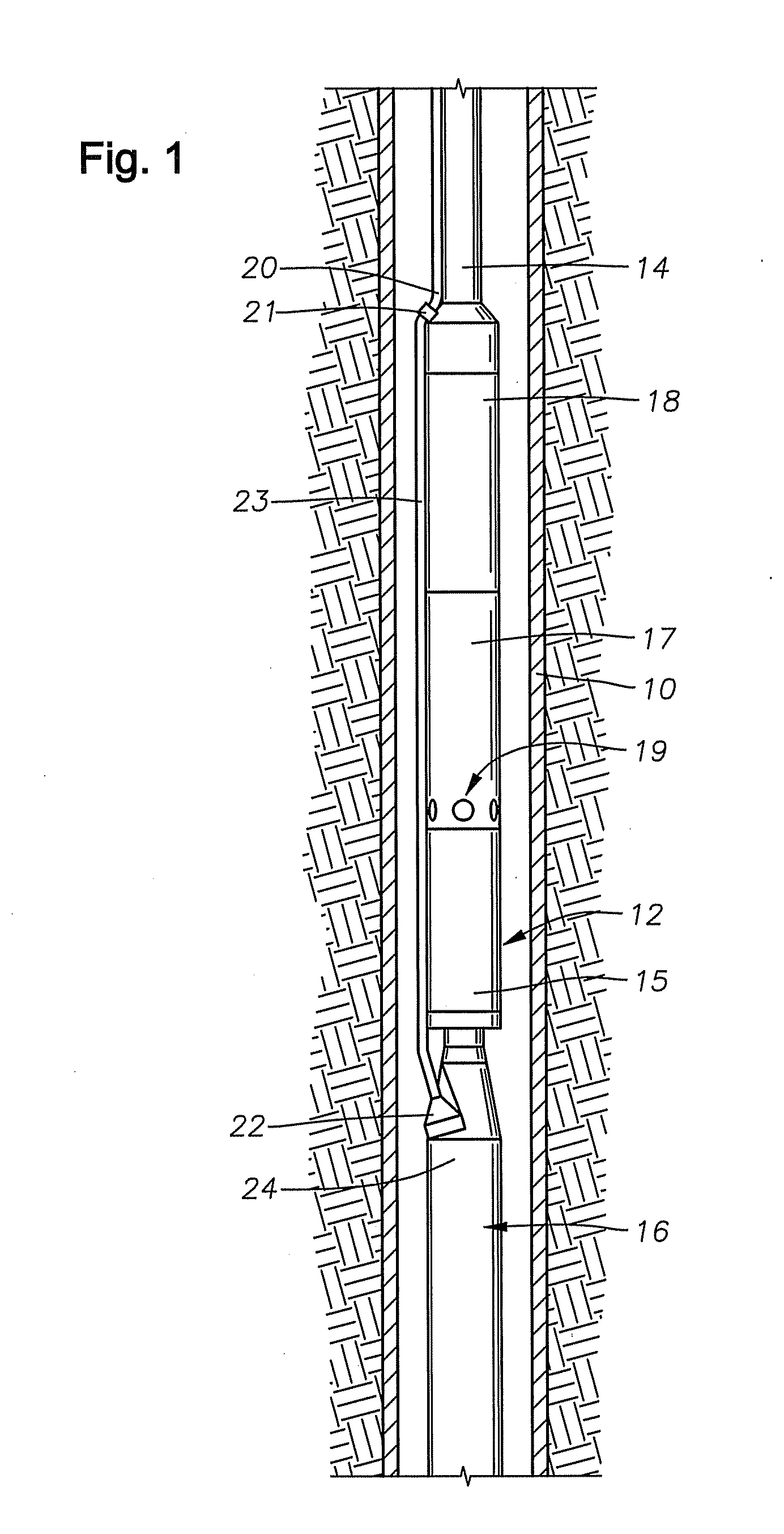
[0027]FIG. 1 is an elevational section view of cased well 10 having an electrical submersible pumping system (ESP) 12 disposed therein. ESP 12 includes an electric motor 16, a seal / equalizer section 15, an optional gas separator 17, and a pump 18. Pump 18 may comprise a centrifugal pump, a progressing cavity pump, or some other rotary pump. Fluid inlets 19 are shown provided on separator 17 for providing a passage for receiving fluid into pump 18. Production tubing 14 is coupled to pump 18 discharge for conveying pressurized production fluid from the ESP 12 to surface.

[0028]Power cable 20 extends alongside production tubing 14, terminating in a splice or connector 21 that electrically couples cable 20 to a motor lead 23. On its lower end, motor lead 23 connects to a pothead connector 22 that electrically connects and secures motor lead 23 to motor housing 24 of electric motor 16. In another embodiment, cable 20 can extend all the way from the surface to pothead connector 22, thereby...


PUM

PropertyMeasurementUnit
Temperatureaaaaaaaaaa
Distanceaaaaaaaaaa

Abstract

Electric submersible well pumping systems operable in well temperatures of above about 180° C. (356° F.) utilize high temperature electrical insulation. The electrical insulation includes E-base polyimide films or perfluoropolymer TE films on various components. The insulation films are employed around magnet wires that are threaded through slots in the stator. Slot insulation of E-base polyimide or perfluoropolymer TE film surrounds the magnet wires in the stator slots. Sheets of E-base polyimide or perfluoropolymer TE film extend around and between phase loops of the magnet wire at the lower end of the stator. The motor contains a PAO oil having additives to dissipate acid generated by epoxy used in the motor.

Description

RELATED APPLICATIONS[0001]This application claims the benefit of provisional application with the U.S. Ser. No. 61 / 382,355, titled “High Temperature Electric Submersible Pump (ESP) Motor” filed on Sep. 13, 2010, which hereby is incorporated by reference in its entirety.FIELD OF THE INVENTION[0002]The present disclosure relates to downhole pumping systems submersible in well bore fluids. More specifically, the present disclosure concerns improved pump motors to drive the submersible pumping systems that can be used in bottom hole temperatures of above about 180° C. (356° F.).BACKGROUND OF THE INVENTION[0003]Submersible pumping systems are often used in hydrocarbon producing wells for pumping fluids from within the well bore to the surface. These fluids are generally liquids and include produced liquid hydrocarbon as well as water. One type of system used in this application employs a electrical submersible pump (ESP). ESP's are typically disposed at the end of a length of production ...

Claims


Application Information

Patent Timeline
IPC IPC(8): F04B35/04
CPCF04B47/06F04D13/10F04D29/026H02K3/34H02K3/345H02K3/38H02K5/132H02K5/225F05D2300/43F05D2300/432F05D2300/434F05D2300/436H02K3/30H01B7/282E21B43/12E21B43/121E21B43/128F04D13/08H02K1/12H01B7/04H01B7/08H01R13/523H01R13/6215
Inventor RUMBAUGH, MICHAEL R.EVENSON, JIM F.REYNOLDS, JACKSON E.KORTE, DAVID G.LIVINGSTON, DAVID W.FREY, JEFFREY G.
Owner BAKER HUGHES INC
Learn More