Electrical Submersible Pump System Having Improved Magnet Wire Leads
- Summary
- Abstract
- Description
- Claims
- Application Information
AI Technical Summary
Benefits of technology
Problems solved by technology
Method used
Image
Examples
Embodiment Construction
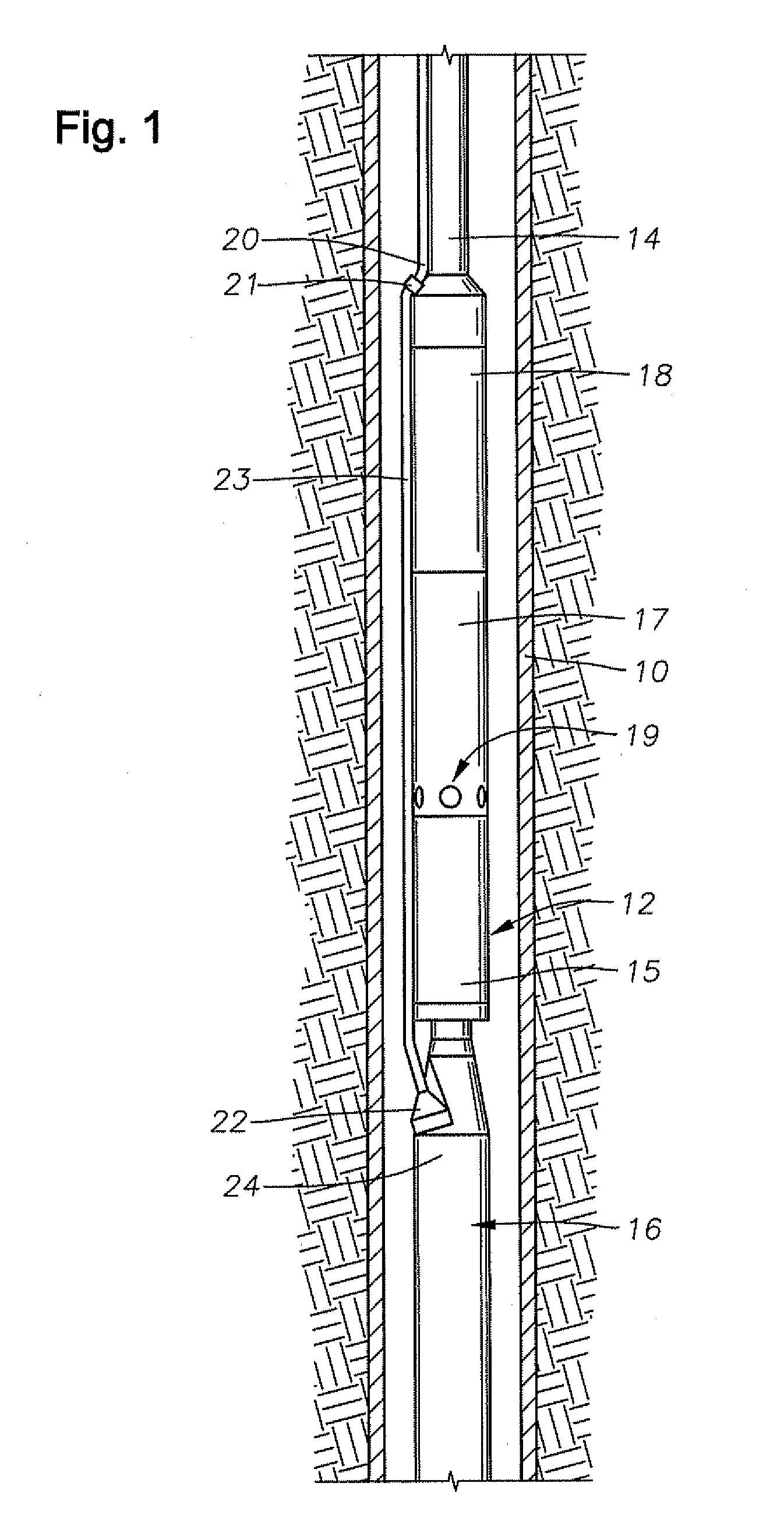
[0031]FIG. 1 is an elevational section view of cased well 10 having an electrical submersible pumping system (ESP) 12 disposed therein. ESP 12 includes an electric motor 16, a seal / equalizer section 15, an optional gas separator 17, and a pump 18. Pump 18 may comprise a centrifugal pump, a progressing cavity pump, or some other rotary pump. Fluid inlets 19 are shown provided on separator 17 for providing a passage for receiving fluid into pump 18. Production tubing 14 is coupled to pump 18 discharge for conveying pressurized production fluid from the ESP 12 to surface.
[0032]Power cable 20 extends alongside production tubing 14, terminating in a splice or connector 21 that electrically couples cable 20 to a motor lead 23. On its lower end, motor lead 23 connects to a pothead connector 22 that electrically connects and secures motor lead 23 to motor housing 24 of electric motor 16. In another embodiment, cable 20 can extend all the way from the surface to pothead connector 22, thereby...
PUM
| Property | Measurement | Unit |
|---|---|---|
| Temperature | aaaaa | aaaaa |
| Temperature | aaaaa | aaaaa |
| Distance | aaaaa | aaaaa |
Abstract
Description
Claims
Application Information
 - R&D Engineer
- R&D Manager
- IP Professional
- Industry Leading Data Capabilities
- Powerful AI technology
- Patent DNA Extraction
Browse by: Latest US Patents, China's latest patents, Technical Efficacy Thesaurus, Application Domain, Technology Topic, Popular Technical Reports.
© 2024 PatSnap. All rights reserved.Legal|Privacy policy|Modern Slavery Act Transparency Statement|Sitemap|About US| Contact US: help@patsnap.com


