Particle beam therapy system
a beam therapy and particle technology, applied in the field of particle beam therapy system, can solve the problem of limiting the number of patients who can be treated, and achieve the effect of improving the number of patients
- Summary
- Abstract
- Description
- Claims
- Application Information
AI Technical Summary
Benefits of technology
Problems solved by technology
Method used
Image
Examples
embodiment 1
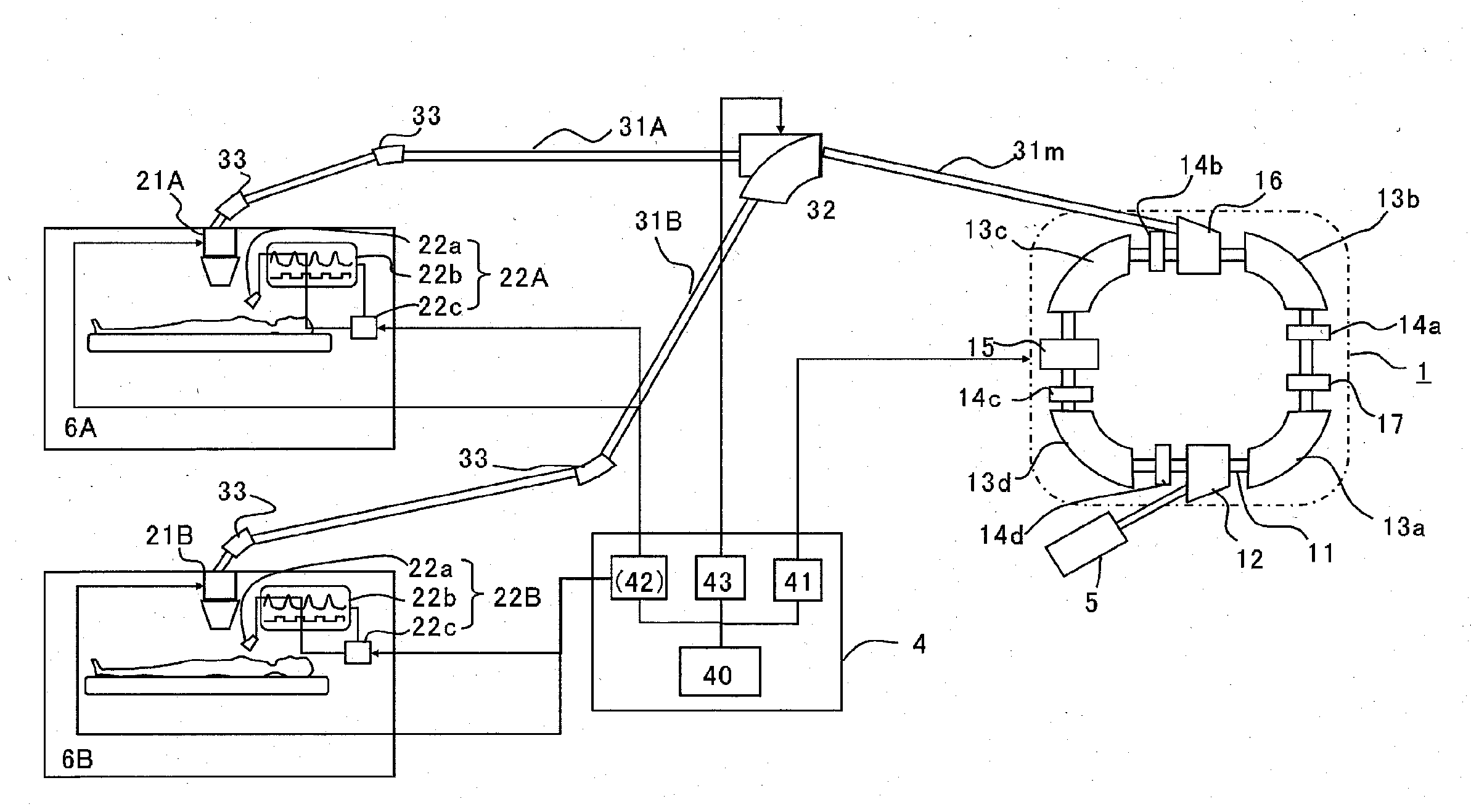
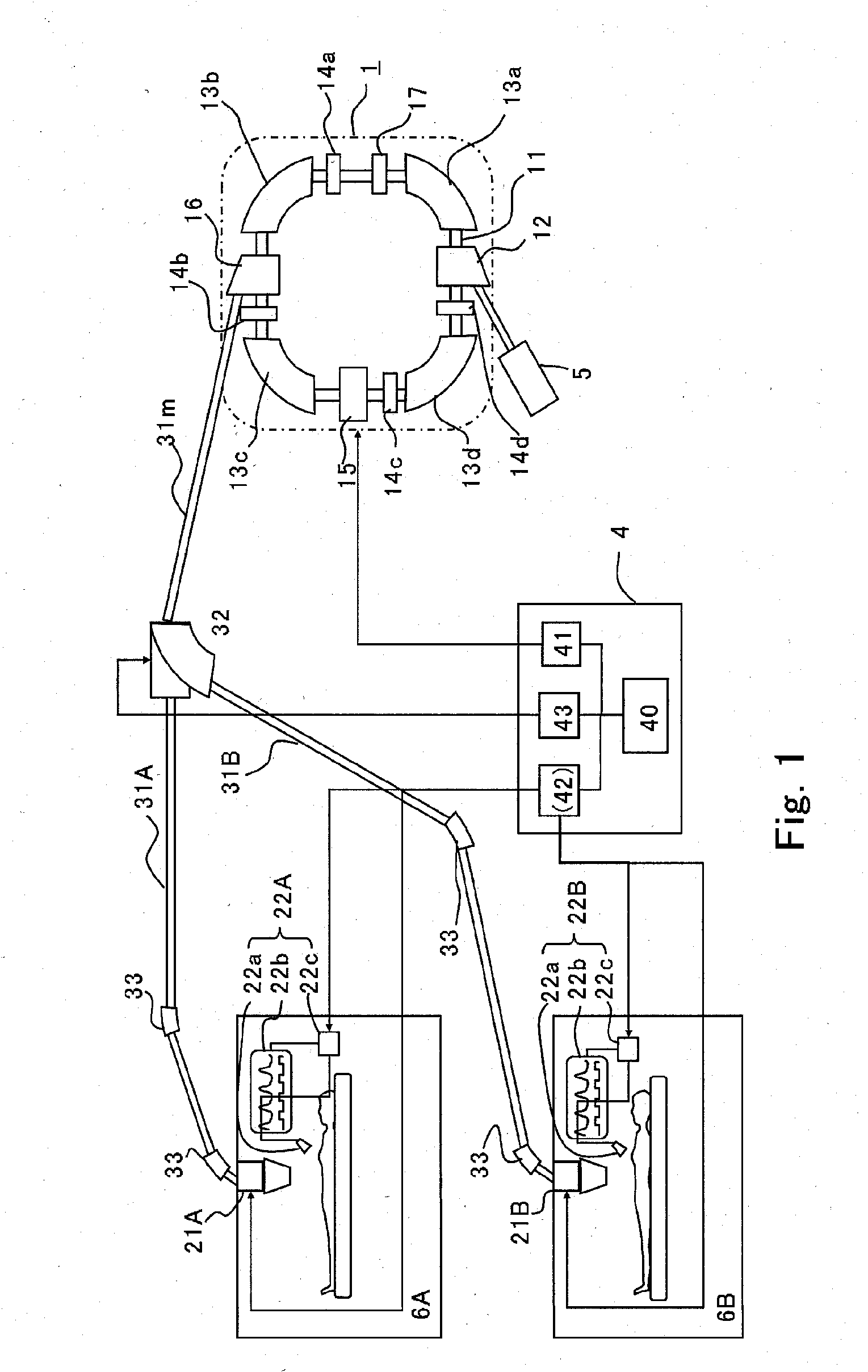
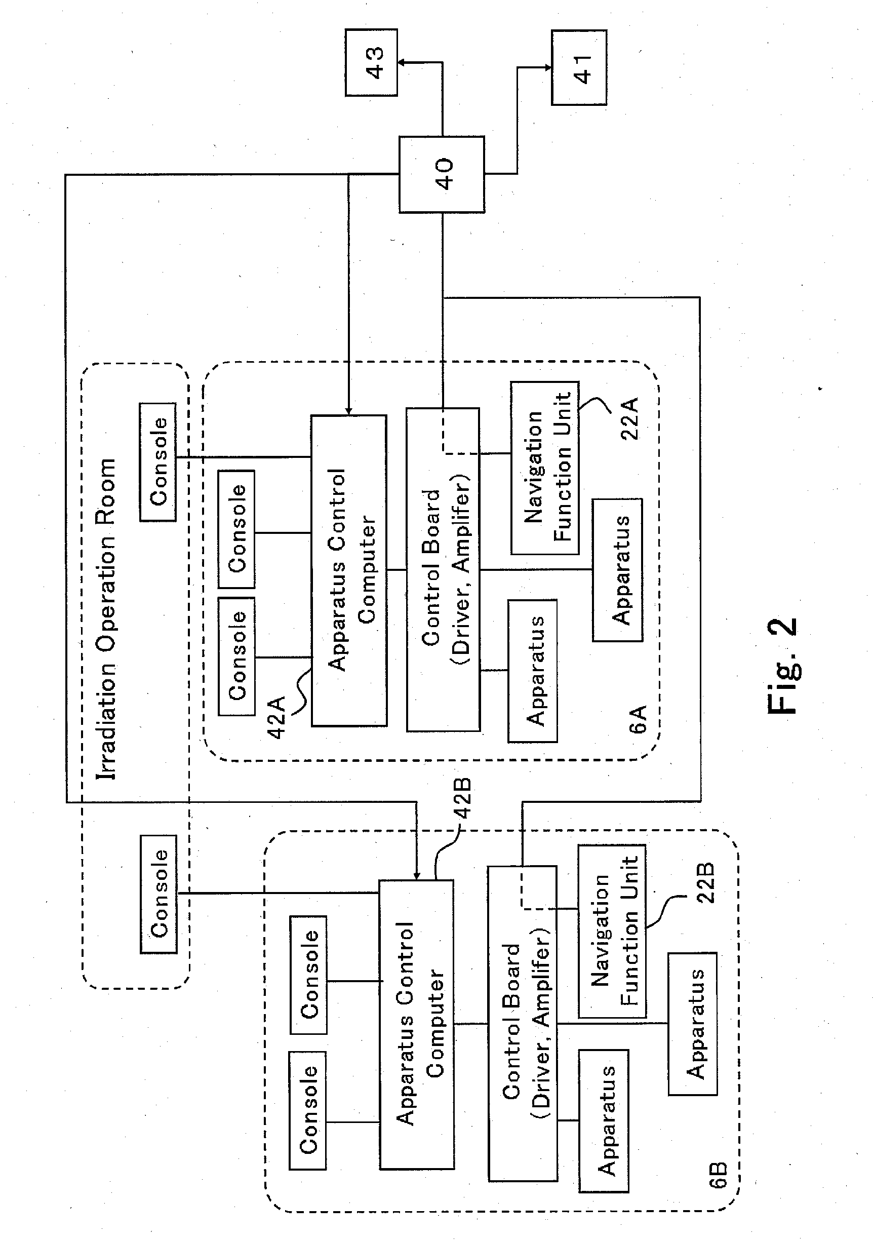
[0017]The configuration of a particle beam therapy system according to Embodiment 1 of the present invention will be explained below. Each of FIG. 1 to FIG. 4 is a diagram, a chart, or a flowchart for explaining the configuration of a particle beam therapy system according to Embodiment 1 of the present invention; FIG. 1 is a diagram illustrating the configuration of a particle beam therapy system; FIG. 2 is a functional block diagram for explaining the configuration related to control of a particle beam therapy system; FIG. 3 is a set of charts representing the respiration navigation in each of treatment rooms and control timings in the transport system of a particle beam therapy system. FIG. 4 is a flowchart for explaining the operation of a particle beam therapy system.
[0018]At first, the configuration of a particle beam therapy system will be schematically explained with reference to FIG. 1. In FIG. 1, a particle beam therapy system is provided with a circular accelerator (just ...
embodiment 2
[0048]In Embodiment 1, there has been described a case where there exist two treatment rooms. However, in general, particle beam therapy systems often include three to four treatment rooms for a single main accelerator 1. Accordingly, in Embodiment 2, there will be explained a case where there exist three or more treatment rooms.
[0049]The following terms can be applied also to Embodiment 1; however, in explaining phase shifts among a great number of treatment rooms, several terms will be defined again.
[0050]As represented in FIG. 3, the desired respiration waveform is formed of a waveform that periodically repeats the same pattern. For example, the local maximum point that indicates a state of inhaling most appears every constant time period. This constant time period is referred to as a “respiration period” (C(A) or C(B), collectively referred to as “C” in units of [sec]).
[0051]As represented in FIG. 3, the desired respiration waveforms WIb(A) and WIb(B) are the same as each other ...
embodiment 3
[0069]In the assumption of Embodiment 1 or Embodiment 2, there has been explained a case where time-sharing irradiation can concurrently be performed in two treatment rooms, i.e., in the case where the duty ratio of the respiration gate signal BG is slightly smaller than 0.5. However, as described above, lowering the duty ratio makes the threshold value Th lower and hence the reproducibility of the position-posture of a patient is raised. In a conventional particle beam therapy system, lowering the duty ratio makes one-time therapy time longer and hence the number of patients who can undergo the therapy is reduced; thus, it is required to keep the duty ration high. In contrast, in the case of a particle beam therapy system, according to the present invention, that adopts time-sharing concurrent irradiation, even when the duty ratio is lowered, the number of treatment rooms where concurrent irradiation can be performed increases; therefore, the stability of the position-posture of a ...
PUM
 Abstract
Description
Claims
Application Information
 - R&D Engineer
- R&D Manager
- IP Professional
- Industry Leading Data Capabilities
- Powerful AI technology
- Patent DNA Extraction
Browse by: Latest US Patents, China's latest patents, Technical Efficacy Thesaurus, Application Domain, Technology Topic, Popular Technical Reports.
© 2024 PatSnap. All rights reserved.Legal|Privacy policy|Modern Slavery Act Transparency Statement|Sitemap|About US| Contact US: help@patsnap.com


