
Apparatus for unbinding a mass of mutually sticked noodles

Active Publication Date: 2012-03-15
SANYO FOODS CO LTD
View PDF20 Cites 2 Cited by
  • Summary
  • Abstract
  • Description
  • Claims
  • Application Information

AI Technical Summary

Benefits of technology

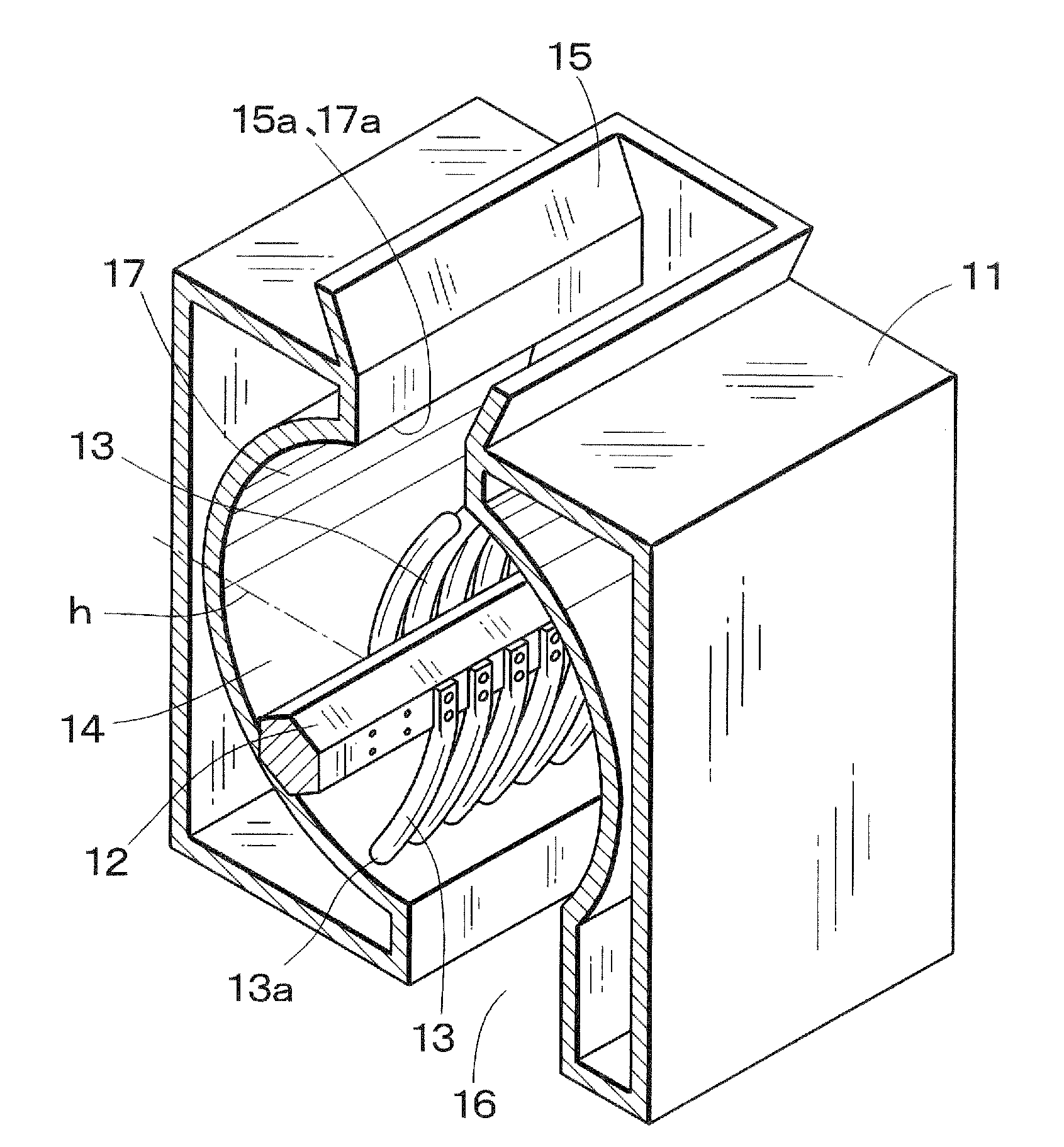
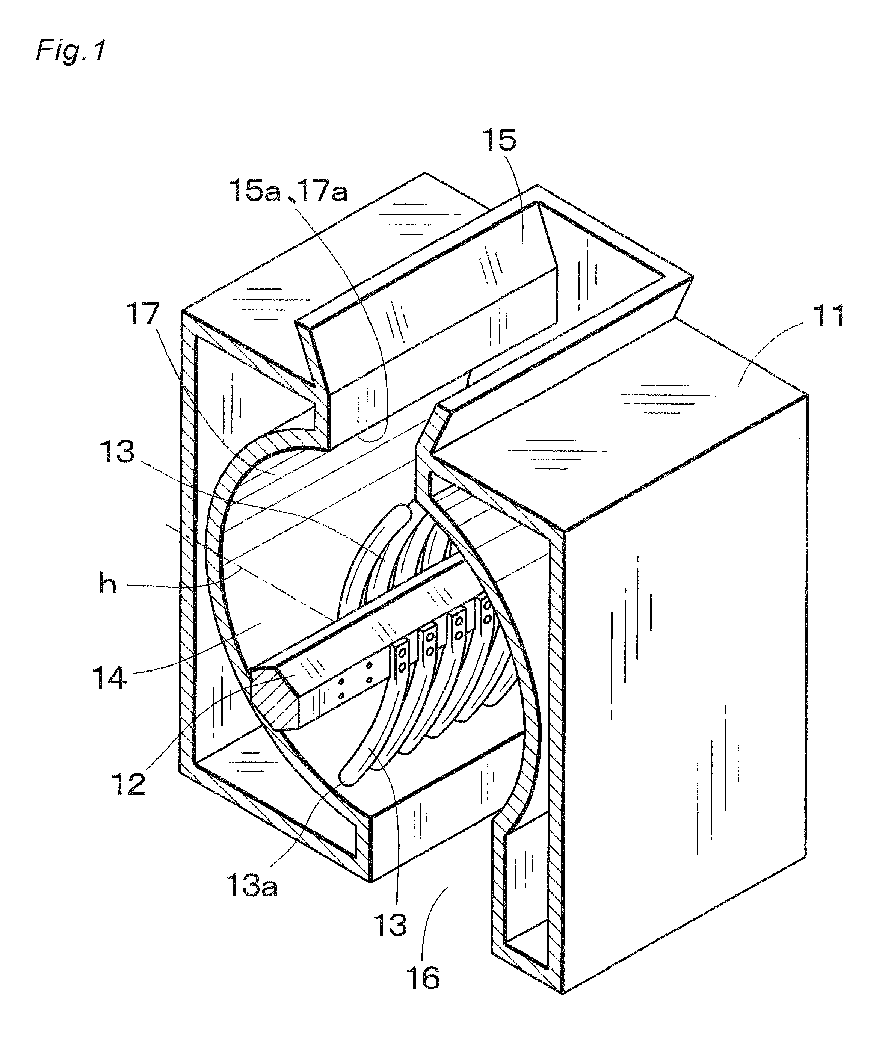
[0010]In the noodle unbinding apparatus according to the invention, a mass of mutually sticked noodles obtained by cutting steamed or boiled noodles to have a given length can be effectively unbound by a cooperation of the unbinding member and the unbinding inner wall surface. In this manner, a mass of noodles having an efficiently reduced degree of binding condition can be obtained.BRIEF DESCRIPTION OF THE DRAWINGS

Problems solved by technology

In the former drying step, noodles are simply folded before drying and the drying process can be carried out at a high speed, but a mass of mutually sticked noodles can not be unbound effectively.
In the latter drying step, a mass of mutually sticked noodles can be effectively unbound, but a production speed is low.

Method used


Image

  • Apparatus for unbinding a mass of mutually sticked noodles
  • Apparatus for unbinding a mass of mutually sticked noodles
  • Apparatus for unbinding a mass of mutually sticked noodles

Examples


embodiment 1

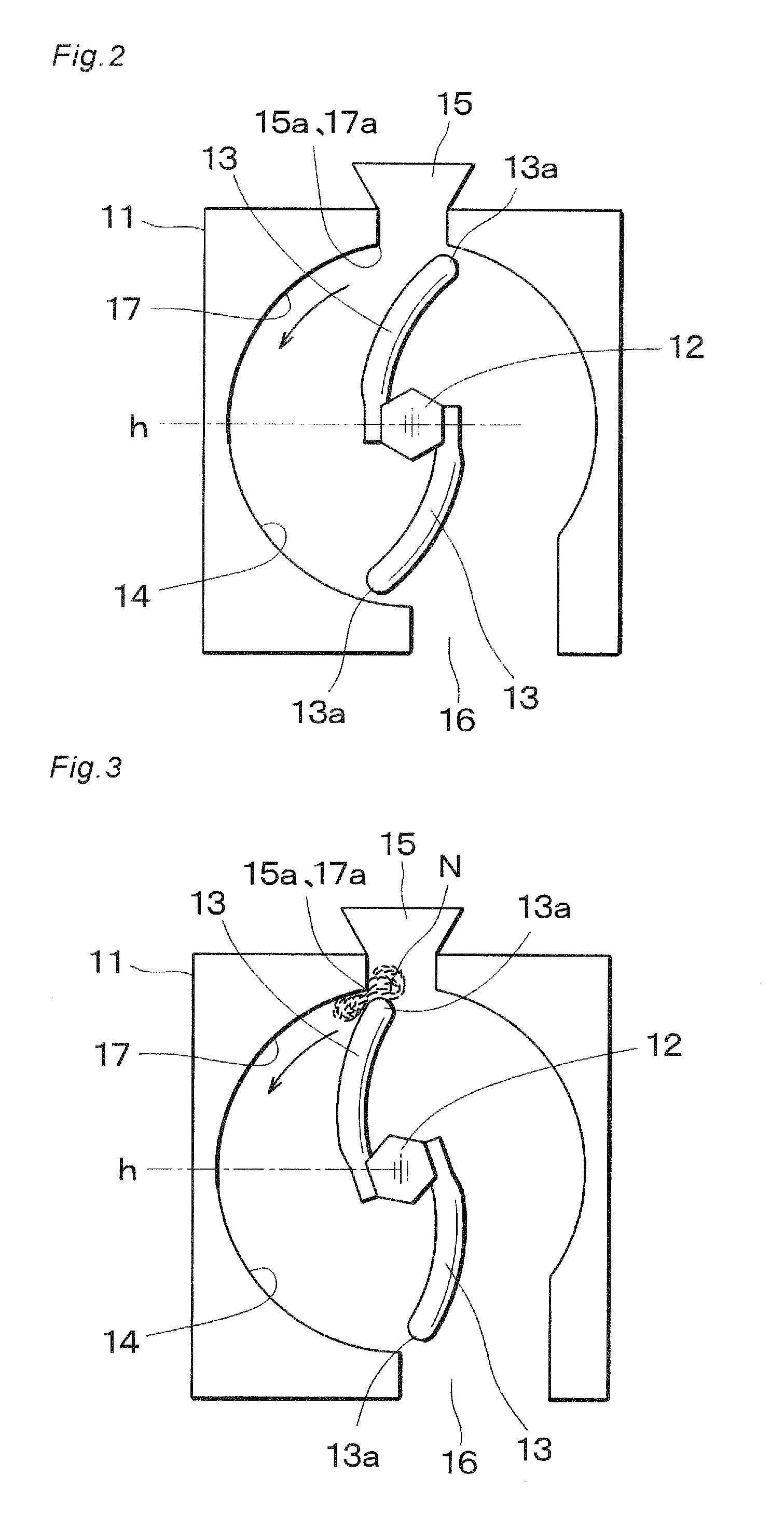
[0028]FIGS. 1 and 2 are perspective and cross sectional views, respectively showing a major portion of a first embodiment 1 of the noodle unbinding apparatus according to the invention. A noodle unbinding step is provided between a streaming or boiling step and a drying step. The noodle unbinding apparatus used in this noodle unbinding step includes a metal housing 11 and a rotating shaft 12 is arranged horizontally at a central portion of the housing 11 such that the rotating shaft 12 can be rotated by an external driving means such as an electric motor not shown in the drawing. In the present embodiment, a pair of unbinding members is secured to the rotating shaft 12 at diagonally opposed positions. Each of the unbinding members is formed by a plurality of noodle unbinding rod 13 formed by a metal rod which having a given length and is bent to project toward a rotating direction of the rotating shaft 12, and these noodle unbinding rods 13 are secured to the rotating shaft 12 to ex...

embodiment 2

[0053]FIG. 11 is a perspective view depicting a major portion of a second embodiment of the noodle unbinding apparatus according to the invention. The unbinding member includes two unbinding plates 18 which are secured to a rotating shaft 12 at diagonally opposite positions. The unbinding plates 18 are curved toward the rotational direction.

[0054]A tip 18a of the unbinding plate 18 has a semicircular cross sectional shape so that a mass of noodles could not be damaged by the unbinding plate. Furthermore, in order to decrease a generation of wind, several holes 18b are formed in the unbinding plate 18.

[0055]As compared with the unbinding rods 13 of the first embodiment 1, the unbinding plates 18 used in the present embodiment 2 have no function to comb the mutually entangled noodles, but a mass of noodles can be effectively unbound by the tips 18a of the unbinding plates 18 in a region near the entrance 17a of the unbinding surface 17 in a similar manner to the first embodiment. Sinc...

embodiment 3

[0056]FIG. 12 is a perspective view showing a major portion of a third embodiment 3 of the noodle unbinding apparatus according to the invention. In the present embodiment, a rotating drum 19 having a large diameter is secured to a shaft 19a and tow columns of short unbinding projections 20 are provided on an outer surface of the drum 19. Each of the unbinding projections 20 has a similar shape as the tip 13a of the unbinding rods 13 of the first embodiment 1. In the present embodiment, the effective unbinding function can be performed like as the first embodiment 1.

[0057]In the third embodiment 3, since use is made of the drum 20 having a large diameter, a mass of noodles might not be dropped toward the rotating shaft 19a even if the rotation speed of the drum 20 is low. It should be noted that the rotating drum 20 may be formed in various shapes such as elliptical shape and rectangular tube shape. In such a case, tops of the drum may be formed as the unbinding member or unbinding ...


PUM


Abstract

Within a housing, a rotating shaft extends horizontally, and curved unbinding rods are secured to the rotating shaft at diagonally opposed positions to extend in radial directions. Within the housing, an inner wall surface is arranged along a circular arc whose center is aligned with an axis of the rotating shaft and whose diameter is slightly larger than a diameter of a circle drawn by rotating tips of the unbinding rods. A portion of the inner wall surface is formed as an unbinding surface having a circular arc cross sectional shape facing the unbinding rods with a small clearance. A mass of noodles for one meal charged into the housing from the inlet is sent in the counter-clockwise direction by the unbinding rods rotated at a high speed and is hit by the unbinding rods repeatedly to perform an effective unbinding function.

Description

FIELD OF THE INVENTION [0001]The present invention relates to an apparatus for unbinding effectively a mass of mutually sticked or entangled noodles which is produced by cutting steamed or boiled noodles to have a given length.RELATED ART STATEMENT [0002]On a mass production line for making instant noodles automatically, there have been provided two drying steps. In one drying step, a mass of noodles obtained by cutting heated noodles are folded, and in the other drying step a mass of mutually sticked noodles are unbound after cutting. These two drying steps have merits and demerits.[0003]In the former drying step, noodles are simply folded before drying and the drying process can be carried out at a high speed, but a mass of mutually sticked noodles can not be unbound effectively. In the latter drying step, a mass of mutually sticked noodles can be effectively unbound, but a production speed is low.[0004]In an apparatus for producing a mass of effectively unbound noodles, there is ...

Claims


Application Information

Patent Timeline
IPC IPC(8): A23N4/04A23L7/109A23L7/113
CPCA21C15/00F26B2210/06F26B1/00
Inventor NAGAYAMA, YOSHIAKIISHIDA, NOZOMU
Owner SANYO FOODS CO LTD
Learn More